SPONSORED CONTENT
As utilities move from traditional off-line, routine testing of power transformer towards on-line continuous monitoring, many benefits are realized. On-line monitoring enhances the safe, reliable operation of substation power equipment, measured performance, reduced failure rates, and provides more consistent and frequent information of the existing fleet. In addition to these benefits the end user realizes improved integration of relevant information so that Operations Managers are better positioned to make more informed decisions.
In this perspective we want to show you the benefits of on-line bushing monitoring, establish what properties you can see and demonstrate why on-line monitoring can be a key tool to help understand the condition of your bushings.
Cigre WG A2.37 [1] established, via a survey of 964 major failures between 1996-2010, that approximately 14.4% of the failures were caused by bushings over all voltage ranges and 47% of those led to fire, explosion and leakages. While we understand off-line monitoring is the most widely applied program, we can demonstrate the benefits of an on-line monitoring system especially when the time taken for incipient faults to develop can be less than the measurement time between off-line inspections. Although we do not see online monitoring replacing off-line monitoring but complementing it – it is another tool in your diagnostic toolbox for early detection of faults that otherwise may go unnoticed until it is too late to correct.
When monitoring bushings there are two main measurements collected – Capacitance change of C1, and Power Factor enabling a customer to understand the mechanical integrity of the bushing core (C1) and assessing the condition of the bushing insulation (PF) respectively. Off-line monitoring can measure these directly. However, these measurements are not systematic and can be affected by change in operator and the presence of contaminants.
Also, off-line measurements are not taken under operational conditions. Conversely on-line measurements are continuous, systematic and are taken under operational conditions enabling better trending of developing faults to mitigate surprise failures of these critical transformer components.
On-line bushing monitoring capturing a Conductive Layer failure
Figure 1 shows a relative change of C1 Trend Chart (left) of a set of three bushings where all three are in very close proximity of each other, as they should be in normal conditions; when C1 % of bushing B suddenly increases by a significant step and then it maintains this deviation against the other two phases.
The Polar Plot (right) offers a different view to the same data where the step change can be more easily observed, alerting the end user of an issue.
Online monitoring enhances the safe, reliable operation of substation power equipment, measured performance, reduced failure rates, and provides more consistent and frequent information of the existing fleet. Online monitoring can be a key tool to help understand the condition of your bushings.
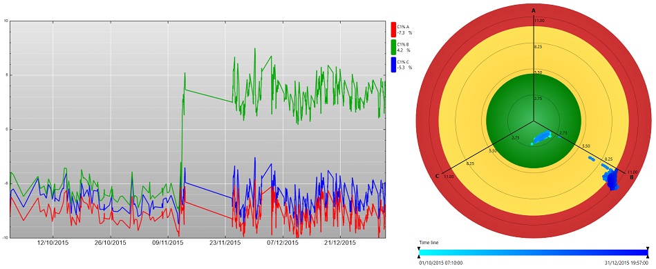
Figure 1. Relative change of capacitance C1: Trend Chart (left); Polar Plot (right)
On-line bushing monitoring capturing an accelerated ageing of the insulation layers
Figure 2 shows an increasing inter-phase angle (as measured at the bushings’ test tap) for the LV phase B (same data shown in Trend Chart -left-, and Polar Plot -right-). This behaviour alerted the user of a rapidly degrading insulation for this bushing.
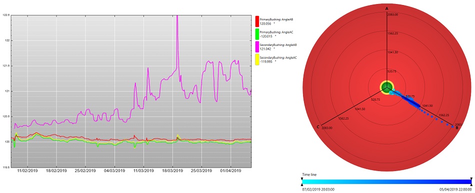
Figure 2. Inter-phase shift increase for LV phase B (indicative of a PF increase): Trend Chart (left); Polar Plot (right)
Benefits of on-line monitoring
The two events (Figure 1 and Figure 2) occurred irrespectively of the monitoring of the bushings. Neither of the respective utilities had planned off-line testing for more than a year after; however, because of the on-line monitor warnings the faults were detected which could have developed into catastrophic failures. Although there is no certainty that this would be the case, it is highly likely that either bushing would have failed before the next planned off-line test. The respective utilities had the time to plan the de-energisation of each transformer, and the bushings were replaced, before developing failure could affect the surrounding assets.
By on-line monitoring, terminal bushing failures became incipient bushing failures [2].
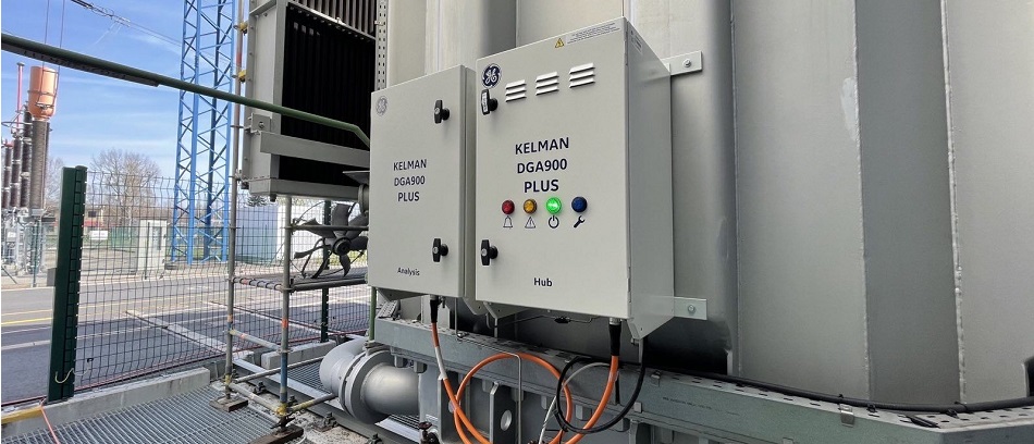
Figure 3. DGA 900 Plus
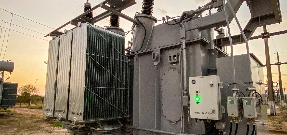
GE’s BMT family continuously monitors the condition of bushings in real-time and provides end users with the information they are used to receiving from off-line tests, namely changes in capacitance and power factor (tan delta), to assess the bushing dielectric efficiency and insulation integrity.
GE’s BMT family continuously monitors the condition of bushings in real-time and provides end users with the information they are used to receiving from off-line tests, namely changes in capacitance and power factor (tan delta), to assess the bushing dielectric efficiency and insulation integrity. This is available as a stand-alone product or available as an integrated solution with our DGA Plus monitor.
References
-
CIGRE brochure 642, Transformer Reliability Survey, WG A2-37, 2015, ISBN: 978-2-85873-346-0
-
CIGRE brochure 755, Transformer Bushing Reliability, WG A2-43, 2019, ISBN: 978-2-85873-457-3
![]()

Dr. Elm Costa i Bricha is a Sr. Lead Electrical Engineer within the GE Renewable Energy group, and currently is the Technical Lead for several NPI projects. He is the Subject Matter Expert on online bushing monitoring and transformer models. Elm grew up in Barcelona (Catalunya), where he studied Physics at the Universitat de Barcelona. He then moved to Belfast where he obtained his PhD in Physics from the Queen’s University. After several years working as a Research Fellow in QUB, he moved to Andor Technologies Ltd. In January 2008 he joined Kelman Ltd (later acquired by GE) working on the field of high voltage asset monitoring using electrical signals, where he specialised on capacitive bushing, partial discharge monitoring, thermal models and OLTC monitoring.

Chris O’Donnell is a Lead Technical Support Engineer for the following product lines DGA 900 and BMT 330. He has been with GE for 11 years and began his GE career as an FSE for our European region. After 3.5 years out in the field he moved into Technical Support role supporting customers for the last 8 years. In the past year he has become a technical expert delivering bespoke BMT training and data analysis. Major projects include delivering customer training to customers in Saudi Arabia & Turkey on the interpretation of data.