FIELD TESTING OF CURRENT TRANSFORMERS
The paper will unfold a systematic approach on how to perform IEEE recommended tests on BCTs safely and accurately in EHV stations. It will discuss how undesired electrical signals from different sources can affect the measurement circuit, and how to mitigate those for ratio and polarity.
Current Transformers (CT), DC power supplies, circuit breakers and relays are key components of the protection and control systems. Reliability of a protection system depends on the performance of these devices. Periodic testing of these assets ensures that the protection circuit that will operate as needed.
Bushing Current Transformers (BCTs) on transformers and circuit breakers are tested as per IEEE recommendations to verify their performance and ensure that they meet manufacturer’s specifications. Testing BCTs is challenging when they are under overhead energized lines, as induced voltages on these bushing terminals affect measurements, this is more pronounced when testing is performed in EHV stations. Article attempts to address this issue by recommending solutions, performing the test as per these recommendations and evaluating results.
IEEE Recommendations for Testing relaying Type CTs:
IEEE Power Engineering Society recommends certain field tests to measure relaying type CTs. These tests are designed to verify proper operation, connection, and condition of the CTs. IEEE Standard C57.13.1, “IEEE Guide for Field Testing of Relaying Current Transformers”, Reference [1] outlines the intention for the designated tests as well as the test procedures. The recommended tests are: Ratio, Polarity, Insulation Resistance, Winding Resistance, Excitation, Admittance, and Burden Test.
Field Challenges of BCTs in EHV Environments:
EHV environments can compound difficulty of testing BCTs. This is a result of a variety of factors, but the most influential is the elevated level of induced voltage. U.S. electric utilities operate complex transmission systems at voltages up to 765 kV. These EHV power lines interact with external objects to create capacitive, inductive, and conductive coupling. This results in induced voltage that can reach several kilovolts. This voltage can be calculated using the equation (2) listed in reference [3]:
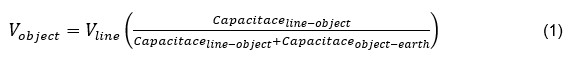
When testing a BCT, the bushing terminals can be left open, effectively insulating the tested equipment from ground. When this occurs, the open-circuit voltage that is induced can be calculated using the equation (3) listed in reference [3]:

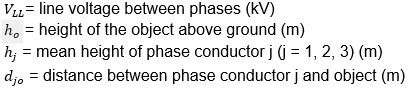
Where:
This induced voltage makes testing BCTs extremely difficult, especially for verification of ratio and polarity. The addition of stray voltage on any floating bushing terminals will drastically change the voltage on the primary winding, making it impossible to accurately measure voltages on the primary. This has been verified by field measurements that result in ratio errors in excess of 10-20%.
Interference and Noise:
IEEE recommended field tests on relaying class CTs are mostly performed by the secondary voltage injection method because of the ease of connections and instrument portability. Measurements for tests such as excitation, winding resistance, inter core coupling and burden are primarily taken on the secondary side of the CT. Since this is electrically isolated from the primary side, interference negligibly affects these tests, and provides acceptable results.
In Figure 1, ratio and polarity tests are the tests where the test instrument’s primary side leads are connected to the bushings of the BCT under test. Since the voltage induced in the CT primary when using secondary test voltage method is just a few volts, it is challenging to measure it accurately under the influence of external electrostatic interference.
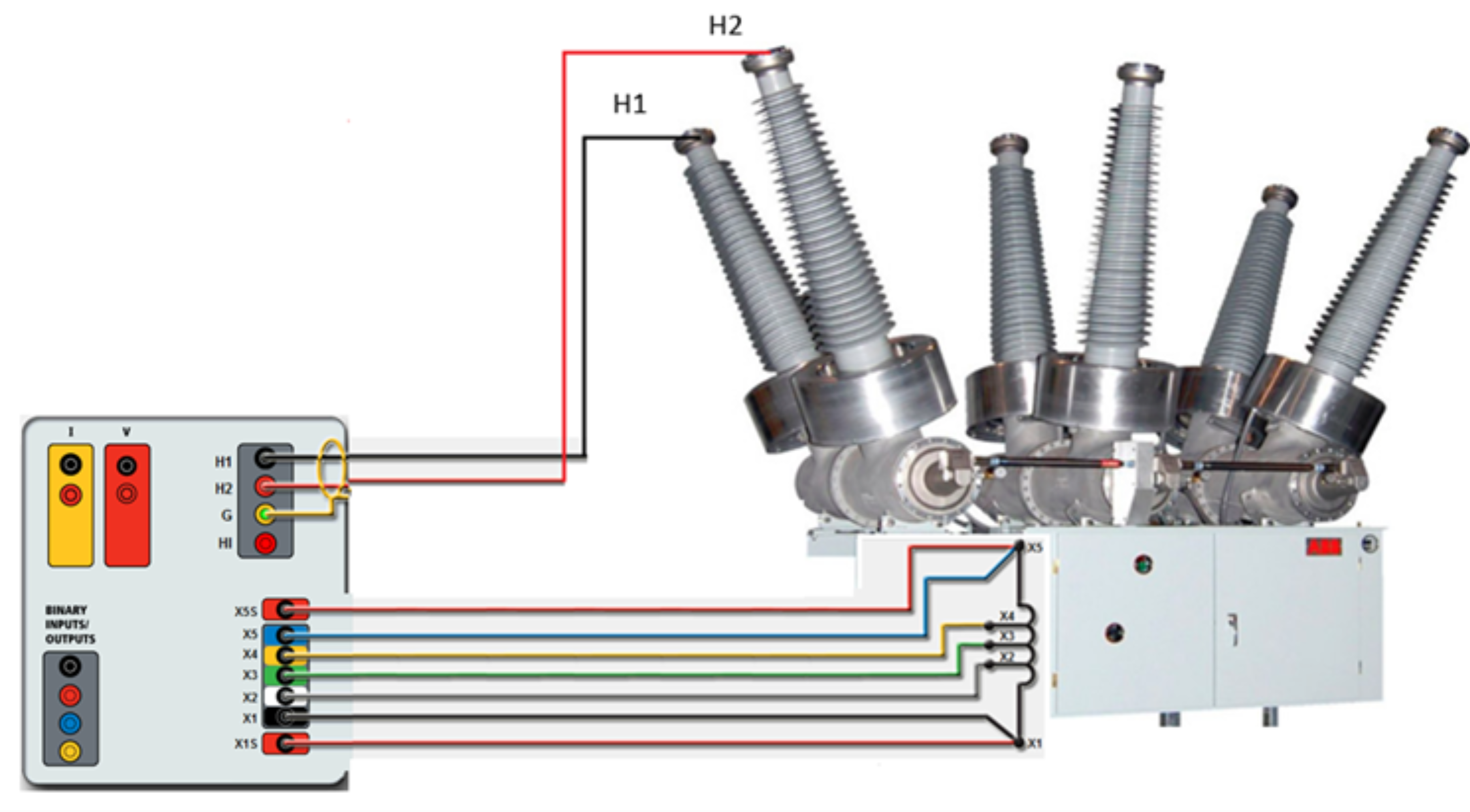
Figure 1: Connections to primary and secondary side of the CT for ratio and polarity test
Interference Suppression Methods:
Transformer equivalent circuit, as per Figure 3.
Primary winding resistance RP and primary leakage reactance XP
Secondary winding resistance RS and secondary leakage reactance XS
Core loss component RC and magnetizing reactance Xm
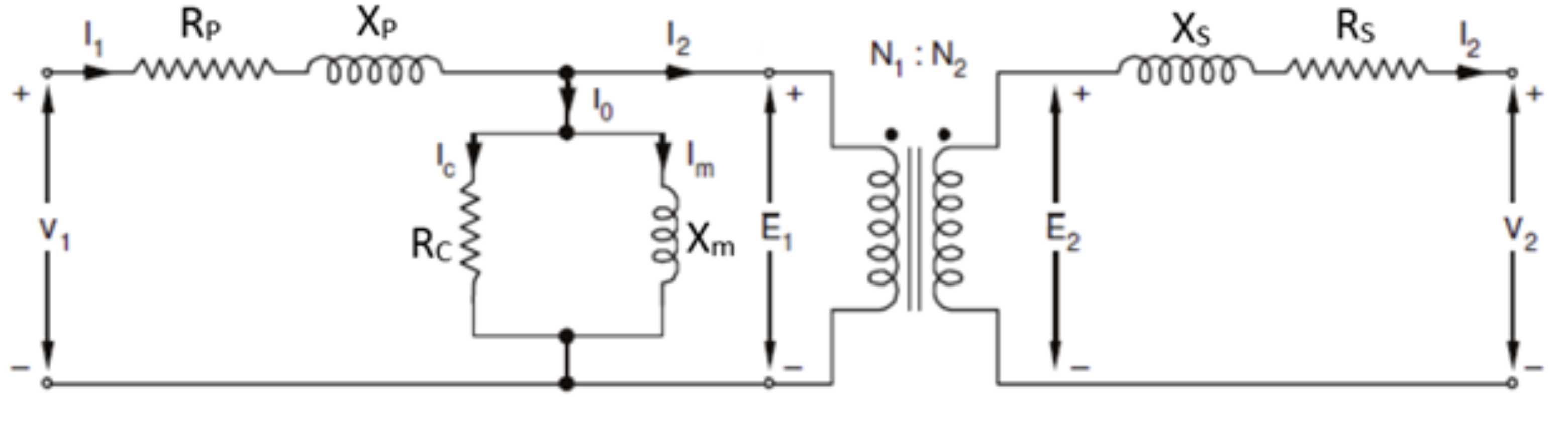
Figure 2: Transformer exact equivalent circuit
Secondary winding impedance when referred to primary side can be represented by an equivalent circuit as shown in Figure 3
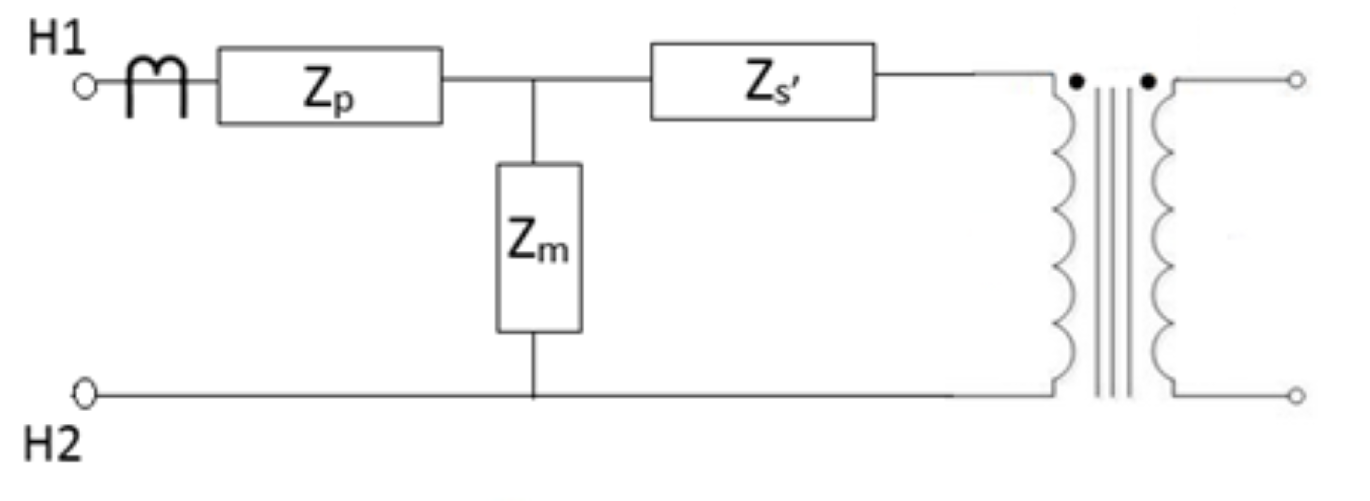
Here,
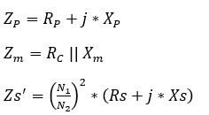
For any transformer, magnetizing impedance Zm is much larger than primary winding impedance ZP and secondary winding impedance Zs’.
![]()
To reduce error in the measurement, reduce the impedance or inductance of the circuit. Under an open circuit condition, the impedance seen by the measuring circuit (as viewed from H1-H2 terminals) is primarily magnetizing impedance as shown in Figure 5. Under an induced voltage condition on the bushing terminals, this can lead to an undesired voltage drop in the measuring circuit and can lead to a ratio error outside the tolerances.
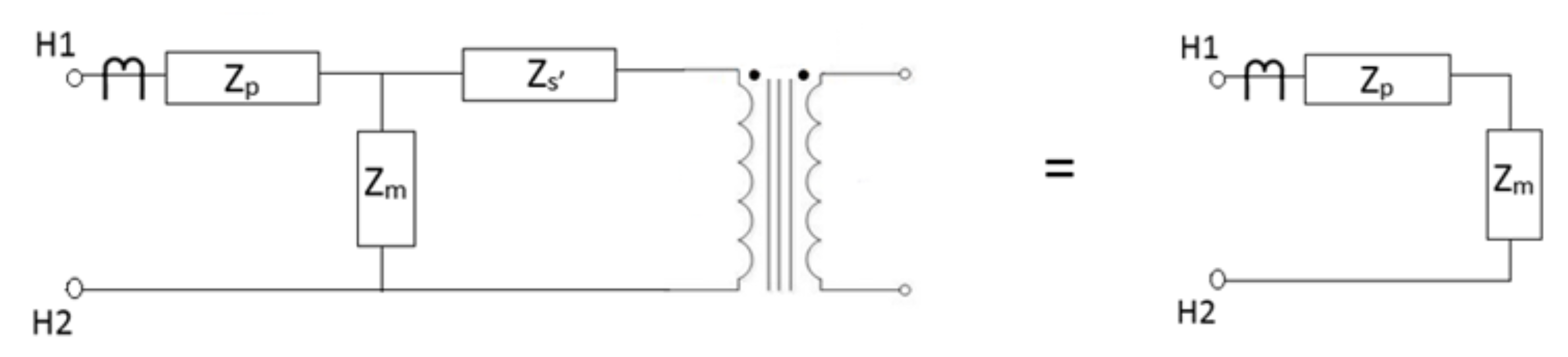
Figure 4: Transformer circuit impedance under open circuit condition
To reduce the impedance of the circuit, it is recommended to short the corresponding secondary winding of the transformer as shown in the diagram below.
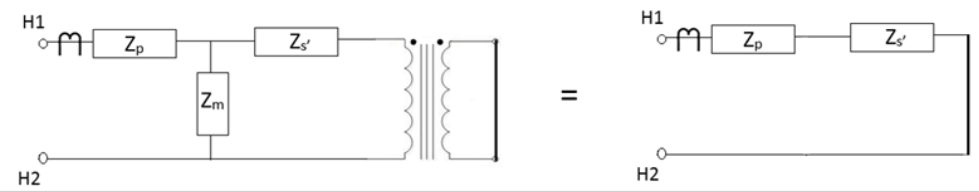
Figure 5: Transformer circuit impedance under short circuit condition
With the secondary winding short circuited, the impedance seen by the measuring circuit is reduced to the primary and secondary winding impedance. The voltage drop across winding impedance is much lower, and this helps in reducing the ratio and phase angle error.
When working under high voltage energized lines, the induced voltage on the bushing terminals and high inductance of the transformer winding together can create a problem. Any induced voltage would cause leakage or stray current through the circuit and with high impedance it would create a higher voltage drop, thereby affecting the measurements. Therefore, in addition to shorting the secondary winding it is recommended to ground the bushing terminal corresponding to the BCT under test to guard against any induced voltage due to coupling effect. Technicians operating the test instrument should be careful in implementing smart grounding principle and avoid any possibility of ground loops which can create a circulating path and influence the current flow in the measurement circuit. It is important to note that only one terminal should be grounded on high voltage bushing terminals to suppress the interference from overhead energized lines. It is also recommended to connect the unused bushing terminals to the return path H2 lead. This serves two purposes; it reduces the effect of any induced stray voltage on the floating terminals and depending upon the winding configuration, it would further reduce the overall impedance of the measurement circuit.
The following diagrams depict the recommended connections for testing BCTs on different transformer configurations:
1) Testing H1 BCTs of a transformer with delta winding configuration is shown in Figures 7 and 8. Connection configurations for all the delta winding bushings are given in Table 1.
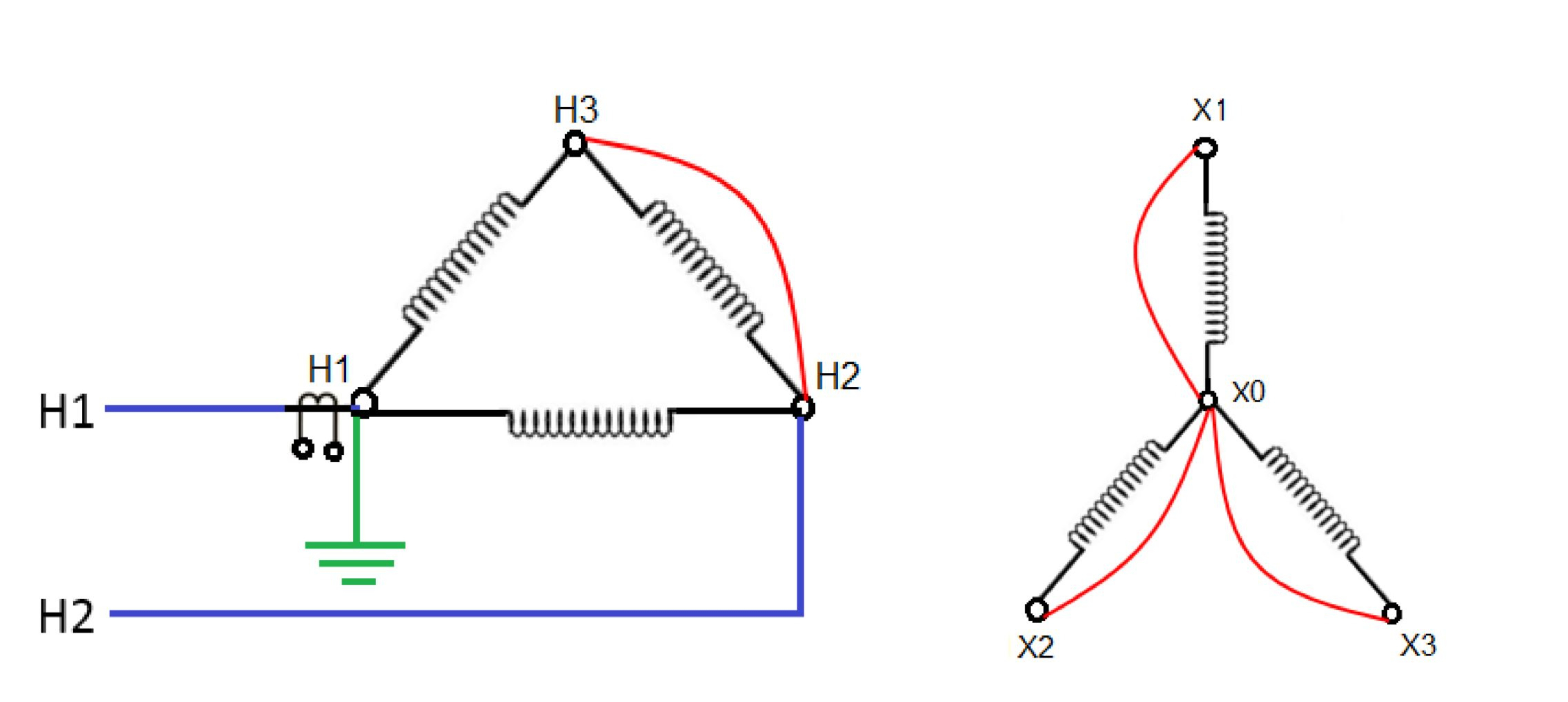
Figure 6: Connection diagram for testing primary side BCTs for a delta-wye configuration
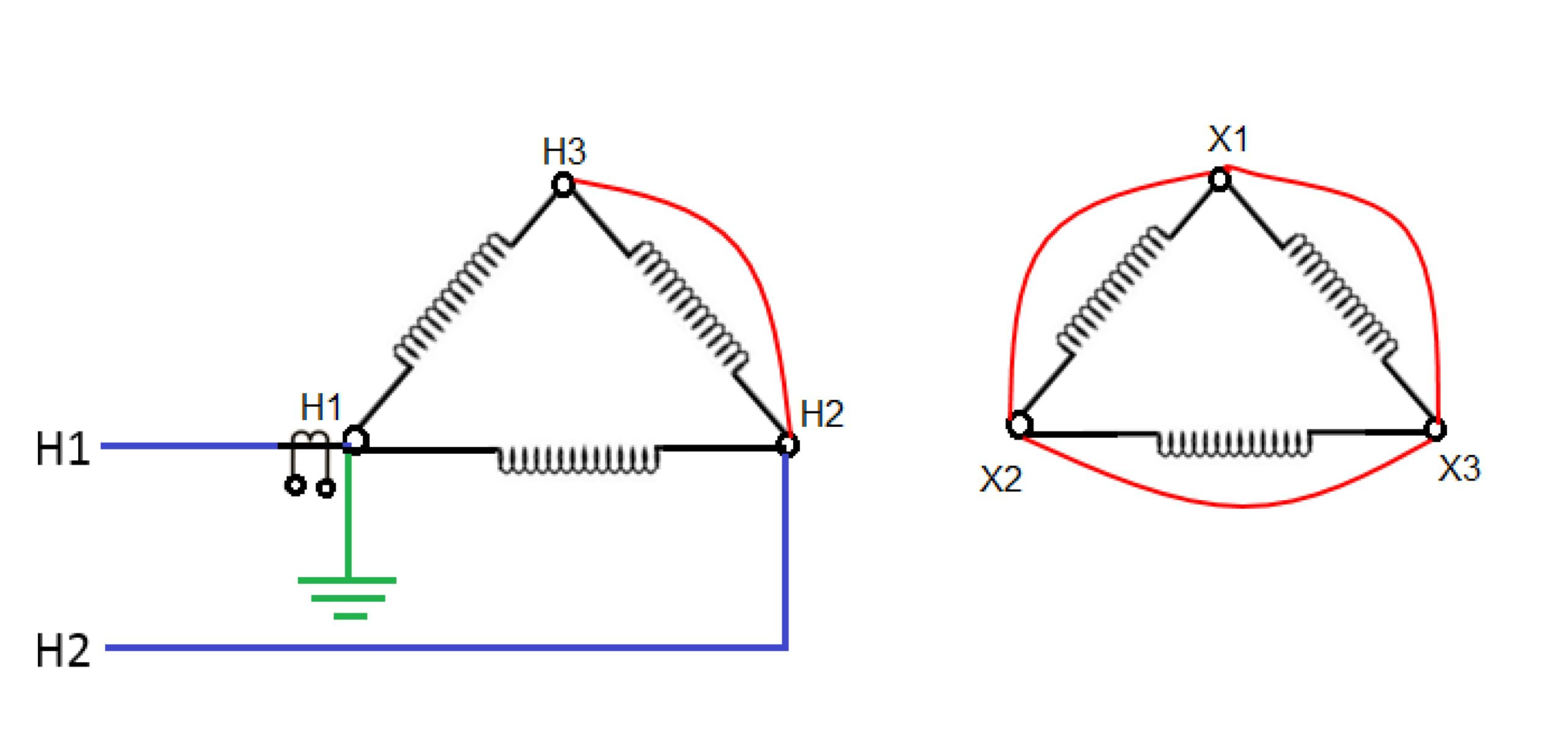
Figure 7: Connection diagram for testing primary side BCTs for a delta-delta configuration
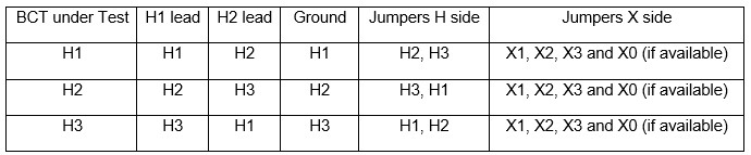
Table 1: Connections for each BCT for a delta configuration winding
1) Testing H1 BCTs of a transformer with wye winding configuration is shown in Figures 9 and 10. Connection configurations for all the wye winding bushings are given in Table 2.
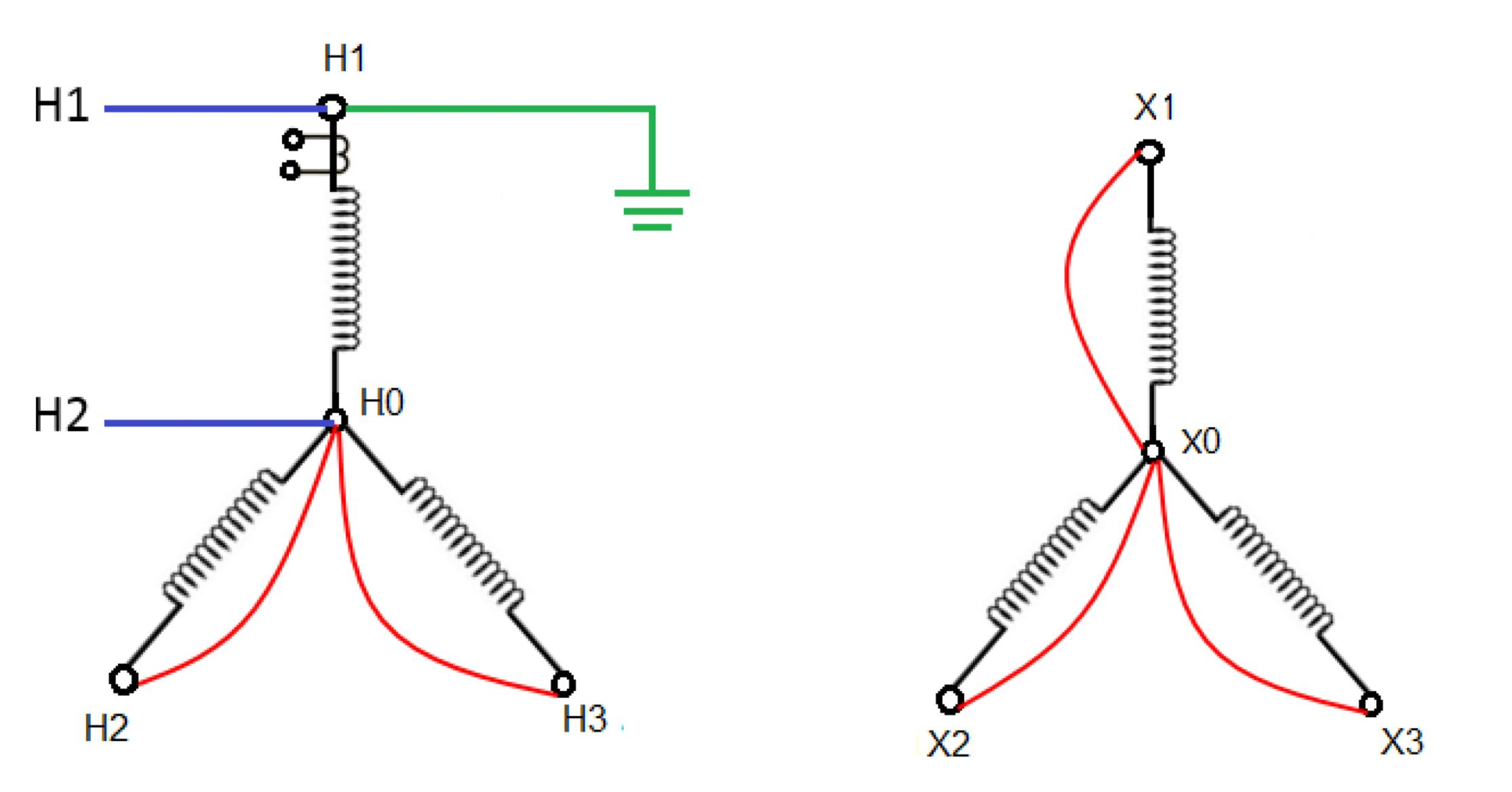
Figure 8: Connection diagram for testing primary side BCTs for a wye-wye configuration
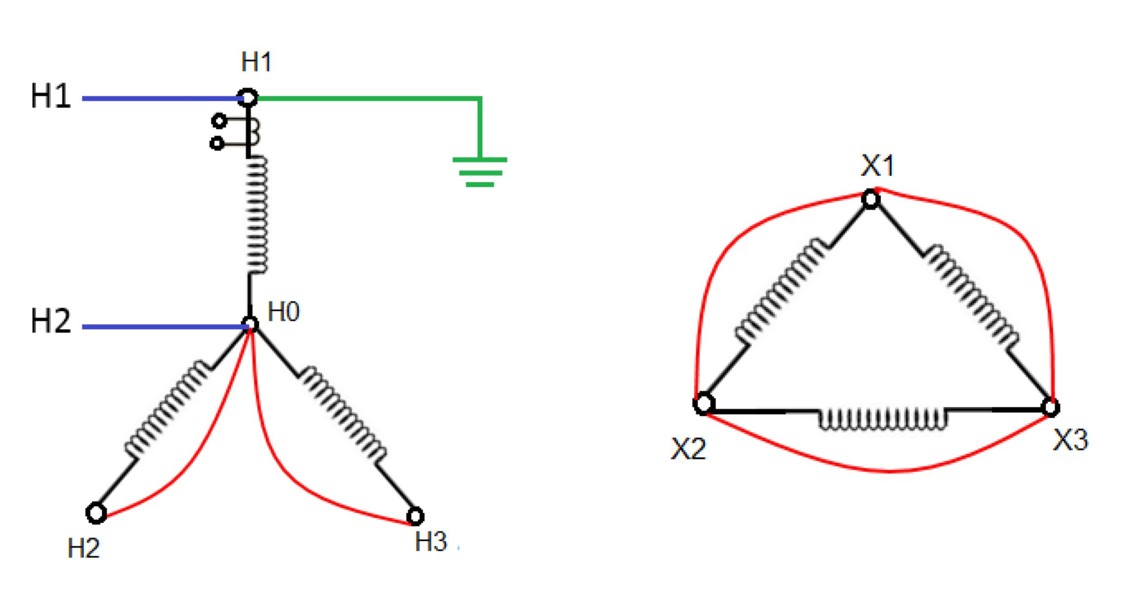
Figure 9: Connection diagram for testing primary side BCTs for a wye-delta configuration
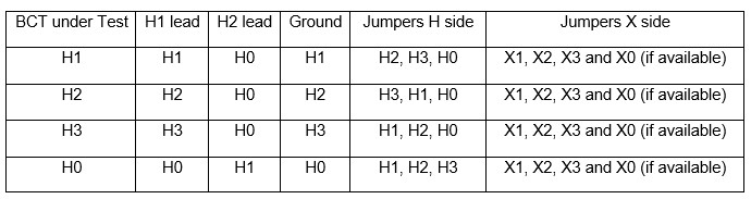
Table 2: Connections for each BCT for a wye configuration winding
3) Testing H1 BCTs of a single-phase auto transformer with tertiary winding is shown in Figure 11. Connection configurations for all the bushings of an auto transformer with tertiary are given in Table 3.
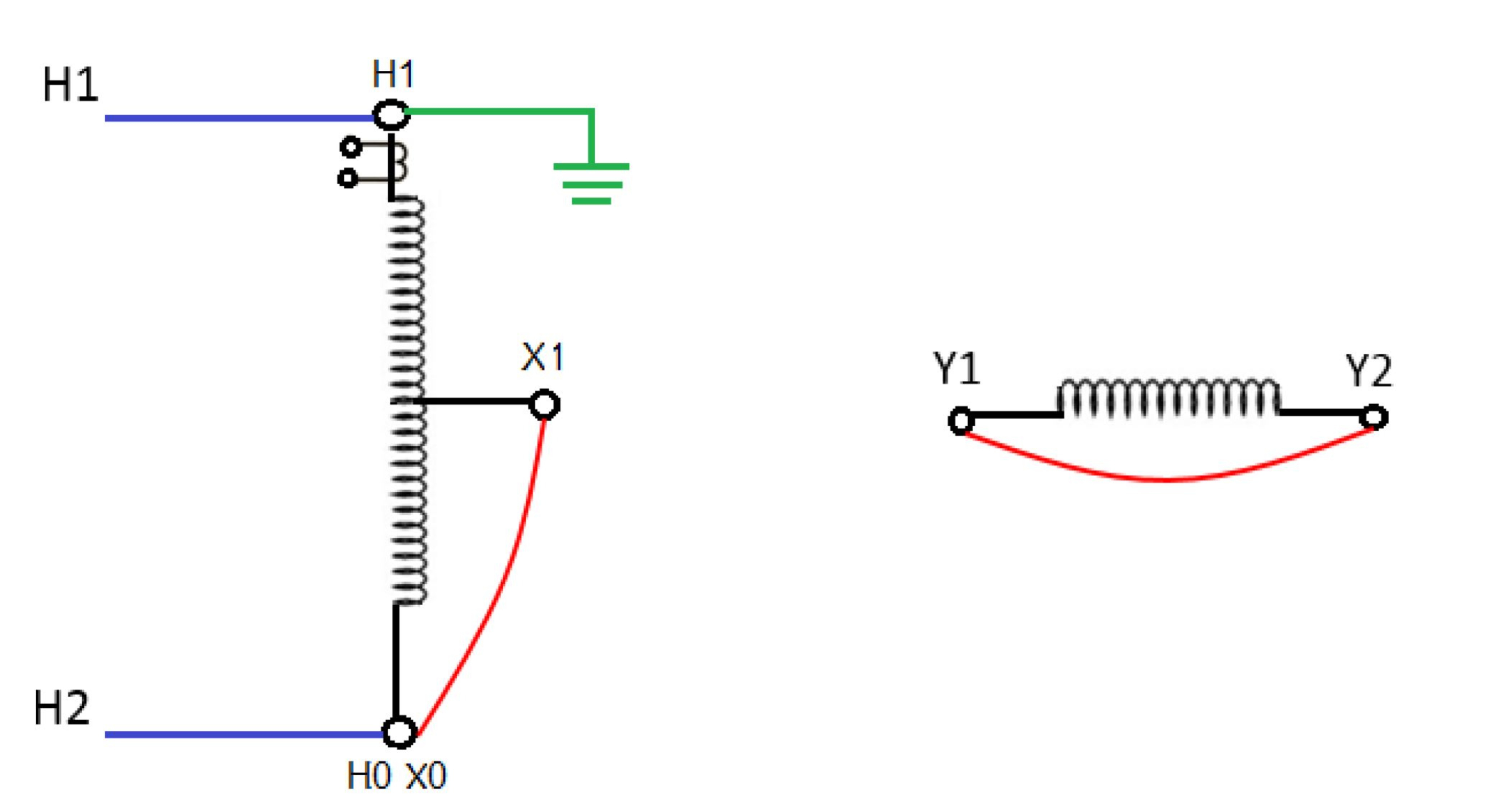
Figure 10: Connection diagram for testing high side BCTs on an auto transformer with tertiary
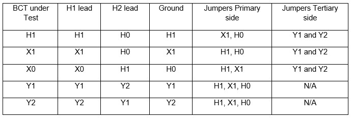
Table 3: Connections for each BCT of a single-phase auto transformer with tertiary
Case Study:
The company in proximity of overhead energized lines and inductance associated with large windings of power transformers were finding it impossible to test BCTs on transformers in their 765 kV substations. The results obtained were inconsistent and unreliable because of copious amounts of error in the measurements. This utility which owns North America’s largest transmission network and operates numerous 500 kV and 765 kV stations, was looking to develop a complete and effective solution to this.
A crucial part of the commissioning process for power transformers in EHV substations is the testing of BCTs. A 765/500/13.8 kV, 750 MVA single phase auto transformer with seventeen BCTs was tested in an energized EHV substation during inclement weather conditions as shown in Figure 12.
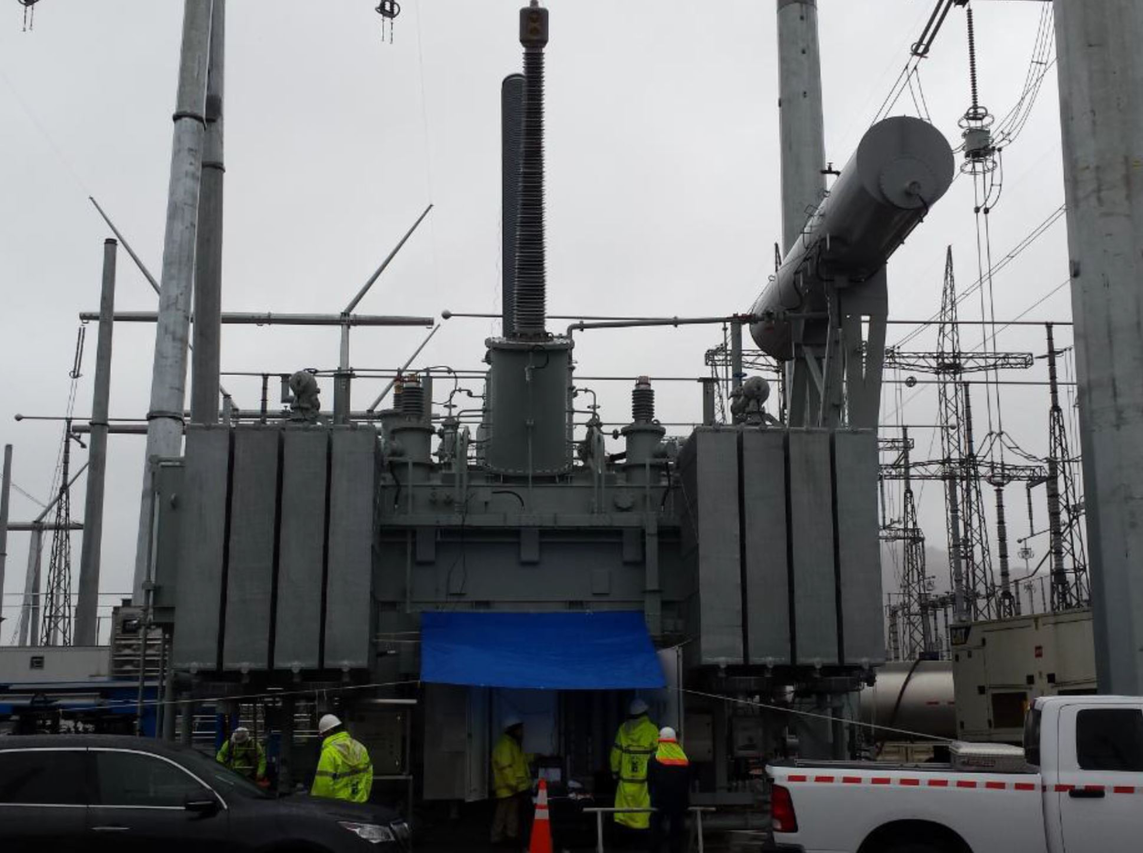
Figure 11: Picture showing the testing under energized lines and rainy condition
As shown in Table 4, a total of seventeen BCTs mounted on different bushings of a single-phase auto transformer with tertiary were tested for all the IEEE recommended tests.
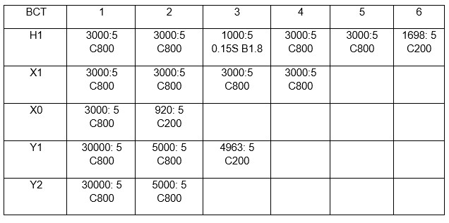
Table 4: BCT with different classes and ratios mounted on different bushings
With cloudy and rainy weather conditions along with the nearby energized lines, conditions were not ideal, where a small measurement error (in the mV range) of high side voltage could have easily thrown the ratio readings off. Insulation resistance was first performed as per the recommended connections in IEEE Standard C57.13.1. When performing the primary to ground insulation resistance test, the test instrument detected a presence of live voltage on bushing terminals and gave a “live voltage present” warning message. The presence of induced voltage and size of the transformer gave indications that test results might get influenced and would pose a challenging situation.
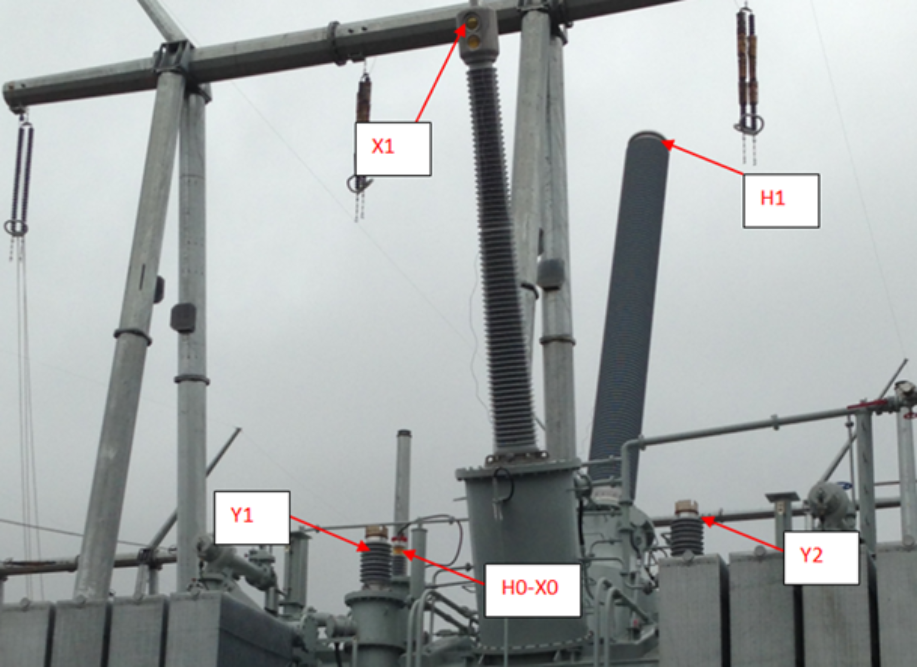
Figure 12: Picture showing the location of each bushing on single phase auto transformer with tertiary
As shown in Figure 13, connections to the bushings were made by bringing a wire from top of the bushing for easy access. The test was first carried out by connecting the leads in a traditional way. Connection, H1 lead to the H1 bushing and the H2 lead to the H0/X0 bushing. All other tests were performed on the BCT without any difficulty. While performing the ratio and polarity tests, readings would not stabilize on high side terminals and manually recording the results gave a ratio error of 20-23%.
To ensure that repeatable and accurate measurements are obtained, three actions were taken:
-
Reduce the effect of electrical noise and electrostatic interference from overhead energized lines by grounding the bushing of the BCT under test.
-
Short the secondary and tertiary winding (separately) to reduce the circuit impedance.
-
Short all the floating unused terminals and connect to the return path (H2 lead).
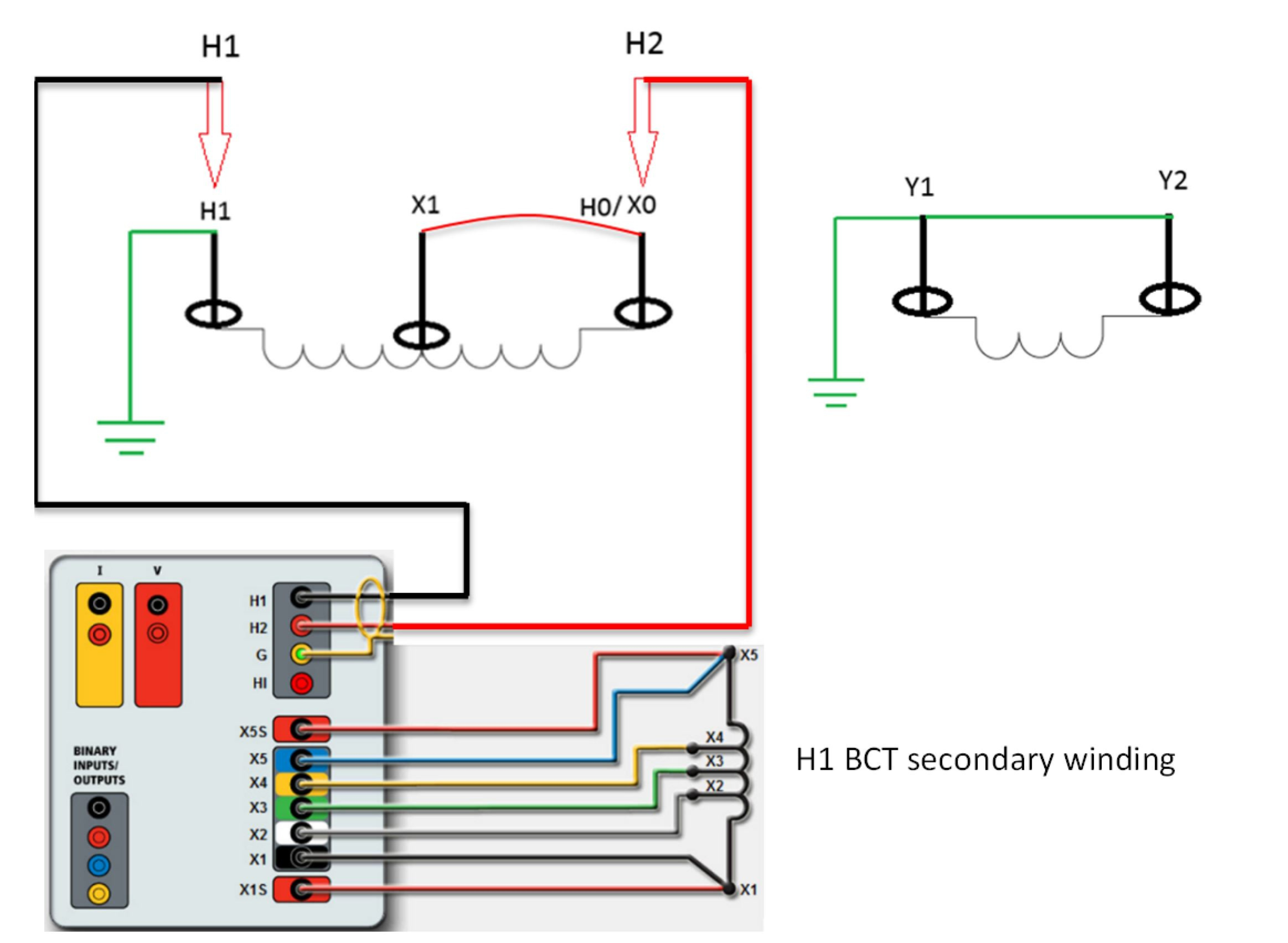
Figure 13: Connection diagram for testing BCTs on single phase auto transformer with tertiary
Using the connections shown in Figure 14, testing was repeated, and consistent results were obtained for all the tests. The following results were on a C800 3000:5 multi-tap CT mounted on the H1 as shown in Figure 15.
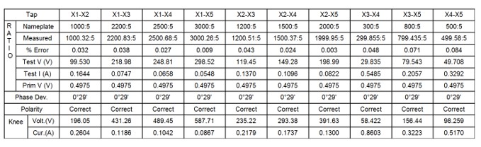
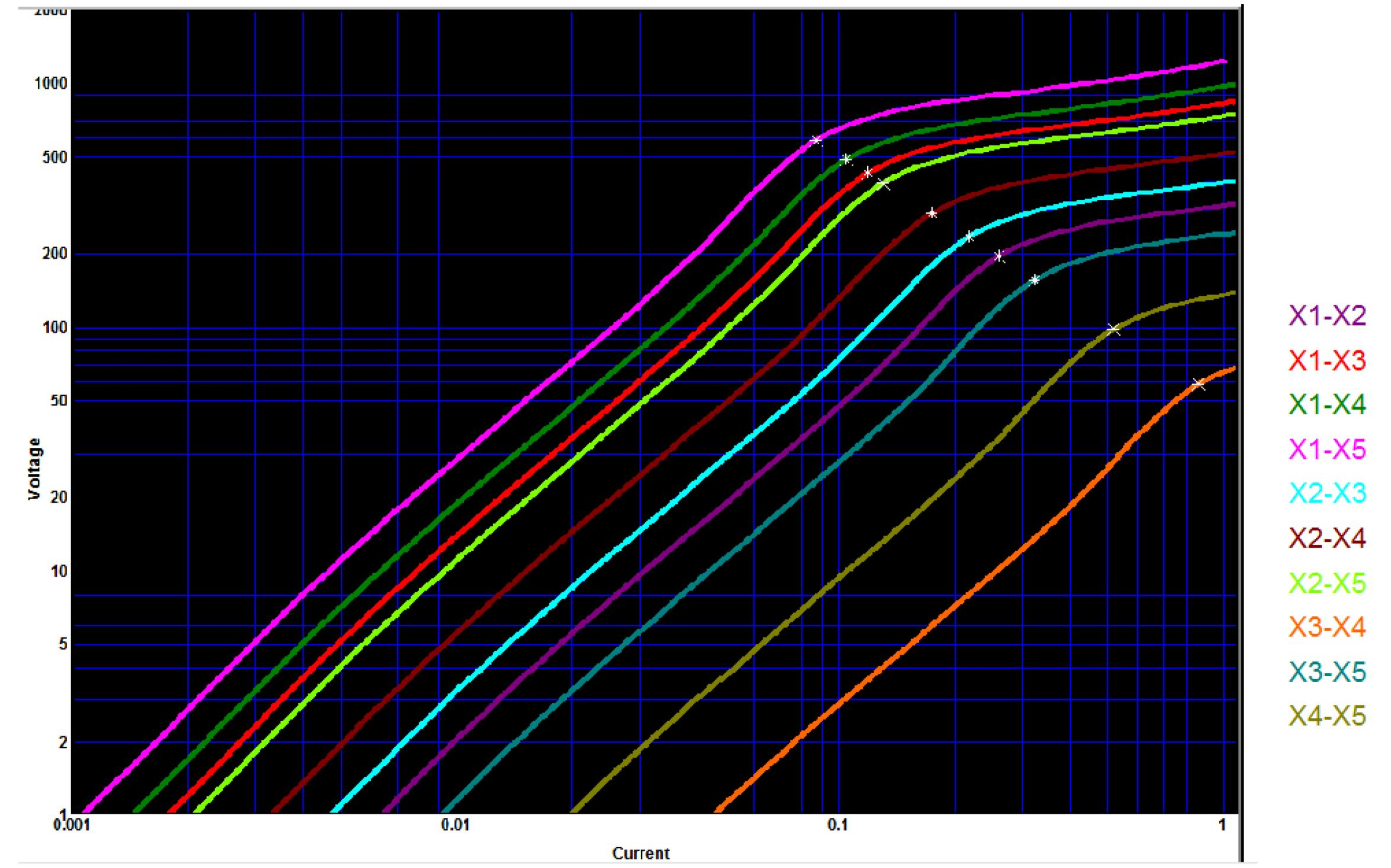
Based on the connections applied for the first BCT, the others were tested using the same procedure and accurate results were obtained on all the BCTs. The results obtained on C800 5000:5 BCT mounted on tertiary winding Y1 bushing are shown in Figure 16.
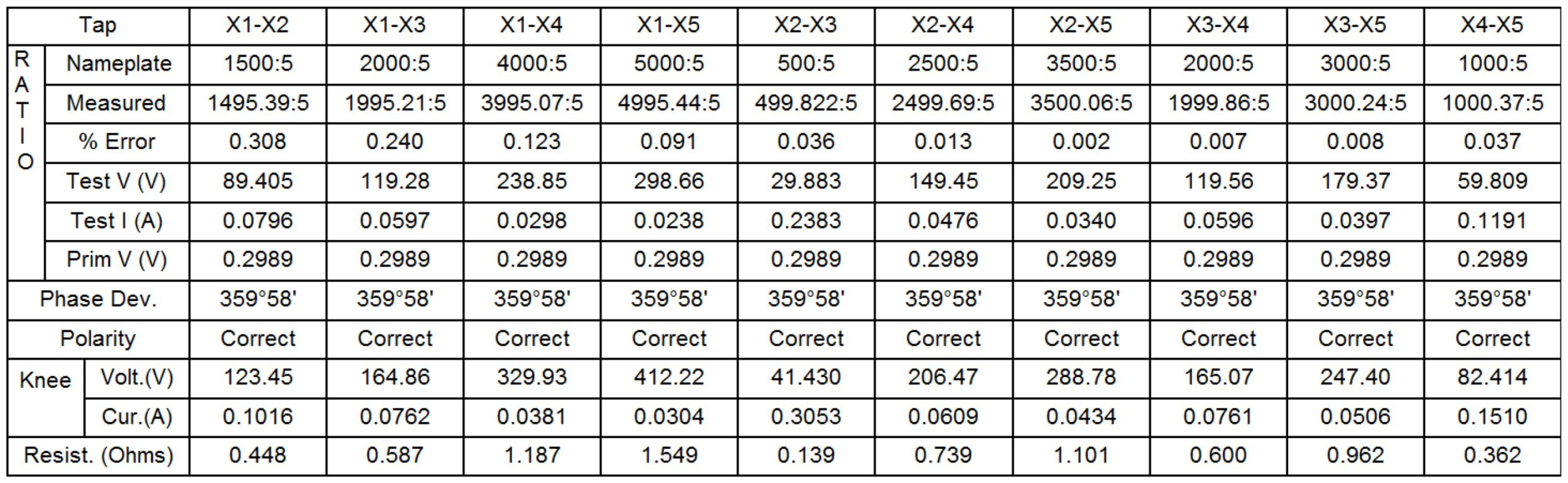
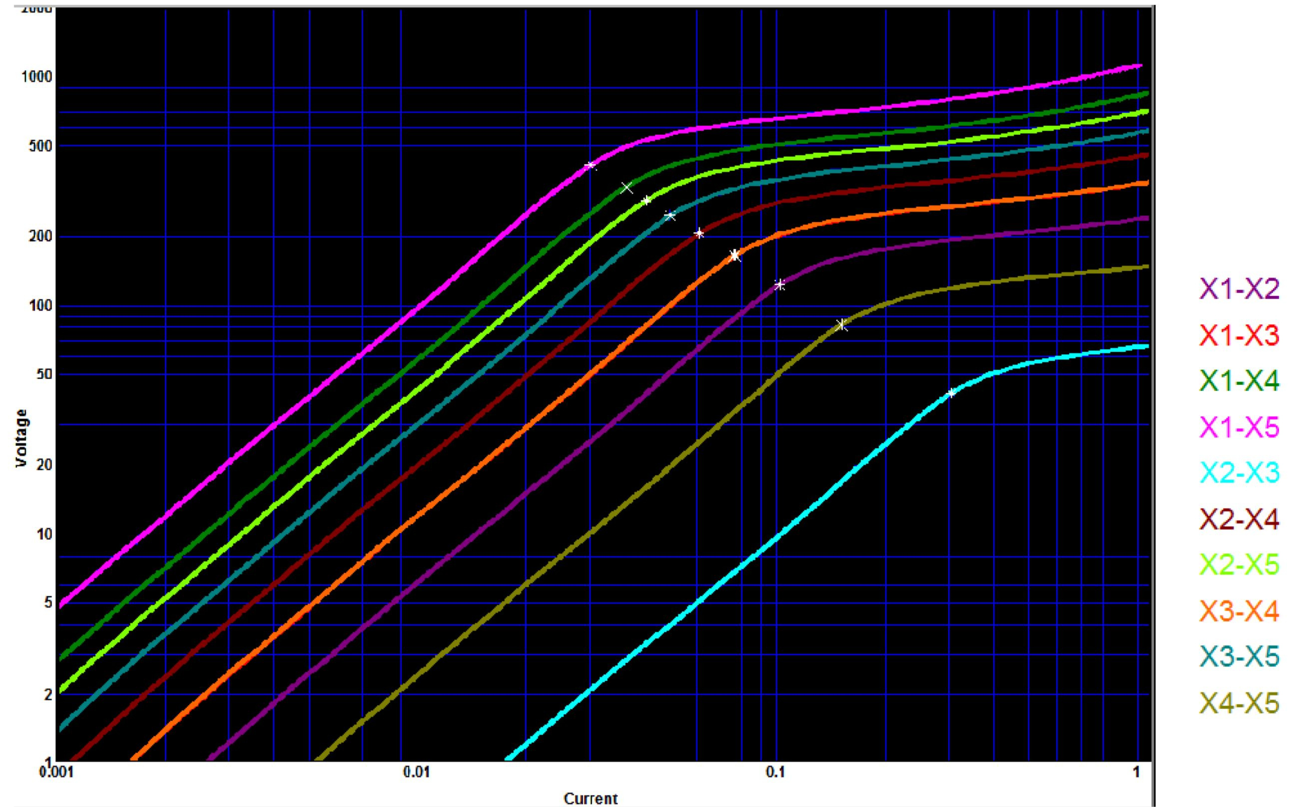
Figure 15: Ratio and Saturation results of Y1 BCT
Three other transformers in 500 kV and 765 kV substations were tested with the same concept and all the CTs ratio and polarity measurements were obtained with high accuracy and repeatability. Overall, more than fifty CTs were tested with the same procedure.
It was noted when working with lower inductance transformer windings where there is little or no interference, some of the recommended steps above could be skipped and reliable measurements are still obtainable.
Conclusion:
Test cases verify effective grounding and isolation techniques can be used to safely obtain highly accurate measurements on BCTs in less-than-ideal environments by eliminating electrostatic build up. This paper outlined measurement techniques for various winding configurations to reduce noise and interference seen in EHV substations. Reduced interference levels provided near perfect accuracy. This allows for precise testing of BCTs as outlined by IEEE.
References:
[1] “IEEE Guide for Field Testing of Relaying Current Transformers”, IEEE C57.13.1- 2006
[2] Diego M Robalino, “A Comprehensive Approach to Current Transformer Field Diagnostics”, TSDOS 2014.
[3] Abdel-Salam, Mazen, Hussein Anis, Ahdab El-Morshedy, and Roshdy Radwan, “High-Voltage Engineering: Theory and Practice”, 2nd ed. New York: M. Dekker, 2000.

Dinesh Chhajer received his Master of Science in Electrical Engineering from University of Texas at Arlington. He is the Manager of Technical Support Group at Megger USA. His responsibilities include providing engineering consultation and recommendations in relation to testing of transformers, circuit breakers and other substation assets. He has presented several white papers related to asset maintenance and testing at various conferences within power industry. He has previously worked as an Applications Engineer at Megger and substation and design engineer at Power Engineers Inc. He is currently a licensed professional engineer in the state of Texas.