
THE SERIES WRAP UP
Foreword from the Editor in Chief
It would seem commonplace that Arc Flash Studies would be in place in facilities where power flows from high voltage to low voltage through a complex series of assets, both electrical and mechanical. While the utility industry understands and leads the way on the value and importance of these studies, I am amazed at how often, when asked about the most recent arch flash study, I hear things like, “Oh, I believe we have that somewhere" or "Yes, we did that about five years ago.” Great, five years works, unless of course you have made ANY changes to the system. And all too often a lot of changes have been made, but the study was not updated. That is the norm, not the exception. Chuck Baker, once again in his unique way, lays out the details of why and how, wrapping up his story of the Smith Factory.
CAST
Andy…………………. Reliability Manager of Electrical Power System (recently hired by Brian, Regional Vice President and head person for Smith Industries plant)
Welcome back and thank you again for continuing to follow the introduction and implementation of the reliability centered maintenance program on the Smith Factory Power System. It’s been a tough process, but I am receiving great support and cooperation and I am happy with the progress.
If you recall, a key portion of our foundation power system maintenance strategy is the Arc Flash Study. In the last discussion we had, I said that I would be covering this key component in this edition.
Let me give you a little detail on why we are doing this so quickly after my arrival.
-
It is legally required by NEC and OSHA. OSHA is addressing arc flash hazards with required estimations for incident energy. This regulation gives strength to citations and essentially requires an arc flash study be performed. The Standard for Electrical Safety in the Workplace, NFPA 70E, states in Article 130.5 that an arc flash study needs to be reviewed every five years or whenever there is a significant change in the electrical system. The five-year interval is a straightforward requirement… and we are not compliant.
-
There are documented instances where OSHA has levied significant fines for non-compliance with arc flash label requirements.
-
It is the responsible and safe thing to do for employees and contractor safety.
-
It could potentially help avoid unnecessary down time of the distribution system due to design issues.
The other key factor is the incredible information that will be gathered from the arc flash study. I have purchased an asset management program that will take all information from our electrical equipment, from nameplate to service schedule to evaluation of all inspection reports and testing results. I am going to use the data gathered as a part of the study and load it into this new program.
Let me walk you through what is and has taken place with our study.
The Arc Flash Process
Let me relay the information that was provided by the PE who was performing our Study. He has many years of experience and I think this will help you to understand the process.
A full Arc Flash Study (which is what we require) is a power system analysis of an electrical distribution system for our facility, which consists of a sequenced series of studies including available fault current calculations, equipment withstand/interrupt rating evaluation, protective device coordination study, and finally an arch flash hazard assessment that incorporates all the information, findings, and adjustments acquired from the previously listed studies.
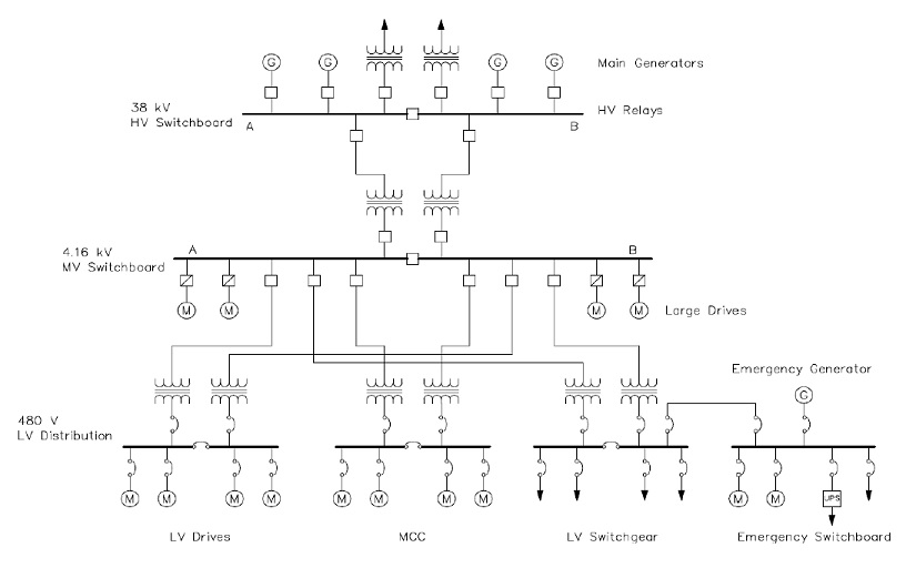 One-line diagram
The process to perform an Arc Flash study begins with the proposal process. In order to estimate the effort and cost involved in performing an Arc Flash Study, the number of busses in a system must be determined. This is sometimes also referred to as the number of nodes in a system. These nodes can either be calculated nodes or non-calculated nodes. A bus or a node is simply a piece of equipment in a distribution system, especially one that might be worked on while energized, such as switchboards, panelboards, disconnects, starters, etc. Calculated nodes are nodes that a fault current calculation will need to be performed for, while non-calculated nodes will not (likely) require a calculation, but still will need an Arc Flash Label.
In addition to the number of buses or nodes, the number of (independent) power sources needs to be determined and identified in the system. These are items such as utility grid ties, generators, PV solar arrays, UPS or battery systems, etc. Finally, large motors (over 50 hp) will also need to be identified and quantified for a given system. Once this has all been determined, an estimate can be prepared for the effort and cost involved with the study.

Once the notice to proceed has been given, the first step in the process involves information gathering. This effort includes getting all information on all equipment such as manufacturer and model numbers. It also includes getting all information on each individual breaker, which again includes manufacturer and model along with all trip settings, if applicable. The size and length of all feeder circuits must be obtained as all this information will be used to accurately model the distribution system.
Finally, information must be obtained about the utility service connection by contacting and obtaining available fault current information at the service entrance location from the utility service representative. Detailed information must be obtained about other independent energy sources such as standalone generators, solar sources, or other alternative energy sources.
This information is now used to construct a detailed model of the distribution system utilizing one of several software packages such as SKM or ETAP. In this model each piece of gear, source, and breaker are entered and modeled using the data and information obtained. If there are multiple sources, the model may need to be created for each scenario to ensure that the worst-case scenario is identified and used in the study. We had an earlier version of a software package and have upgraded to the latest version. In the specification I specified the software we require.
Once the models are complete, the first study that is performed is the faulty current analysis. This is done using the functionality of the modeling software and it is run for each scenario to determine the worst-case available fault current at each location or bus or node in the system. The equipment evaluation study is done in conjunction with the available fault current analysis to ensure that each protective device in the distribution system is adequately rated to interrupt the circuit in the presence of a fault condition. This analysis and evaluation are done using the modeling software such as SKM or ETAP and the available fault current information provided by the local utility company at the service entrance point.
Next, each distribution pathway or feeder from the main service is modeled, and all overcurrent protective devices in each feed are mapped concurrently to examine how these devices will coordinate with each other in the event of an overcurrent situation. The goal is to adjust the settings of the breakers, when possible, to ensure that the overcurrent device closest to the load that is in overload will trip first – so that any unnecessary nuisance tripping further up the line closer to the service entrance is avoided to minimize the outage area in the event of a trip due to overload.
Finally, once all recommended breaker adjustments are approved and implemented, the entire distribution system is modeled to determine incident energy values at each node or bus equipment location, so that an Arc Flash Hazard assessment can be performed. This assessment will determine Arc Flash Boundaries, inside of which personnel working on energized equipment should wear appropriate Personal Protective Equipment (PPE). The incident energy values enable a determination of the appropriate PPE required to be worn by service personnel according to current standards. The appropriate PPE descriptions will be displayed in the results of the Arc Flash Hazard assessment tables. The calculated incident energies are then used to determine the recommended PPE level category that is associated with each condition. These PPE categories are separated into six possible categories of Dangerous and Levels from 0-4.
Equipment classified as Dangerous is beyond the established current PPE protection levels and working on this equipment when energized is extremely dangerous and not recommended.
Level 4 is the most dangerous category that allows for working on energized equipment and requires the greatest amount of PPE protection, which typically results in the service personnel wearing a bee-keeper type suite that is rated to withstand typical arcing faults of this magnitude.
Level 0 is the least dangerous category that requires the minimal amount of PPE when working on energized equipment.

Warning labels for equipment are produced so that they clearly identify the current PPE category, the associated hazards, and the appropriate recommended PPE that should be worn by service personnel when working on the equipment while energized.
If there is equipment that requires a recommended PPE rating of Level 3 or greater, mitigation improvement recommendations will be given to reduce these levels when available. These recommendations will be limited to changes that are typically easy and cost effective to accomplish, such as breaker settings adjustments or fuse replacements. This is another real benefit of this exercise.
Potential Issues or Problems
There are several issues or problems that may be discovered or identified during these types of studies. Some of these issues may include:
-
Insufficient interrupt capability of existing equipment in the presence of the available fault current calculated during the study. This is an extremely dangerous finding in that it indicates that if a fault condition is encountered, the existing gear may not be able to clear the fault or de-energize the circuit which could result in the injury or death of personnel, and/or serious damage of equipment.
-
Improper coordination of overcurrent protection devices. This is a problem in that if an overload condition is encountered, there is the potential for a breaker upstream to trip before the more localized breaker trips. This increases the impact scope in the distribution system, which usually increases the impact area of a process.
-
Improper breaker coordination accounting for inrush current in large transformers. In the device coordination study, the damage curves and inrush current for each transformer are included in the trip curve analysis for each feeder. If the breaker settings are not set correctly in relation to the transformer characteristics, inrush conditions could cause nuisance tripping. In addition, if transformer damage curves lie inside the trip ratings of related breakers, the transformer could incur damage under certain conditions.
-
Danger to employees working on energized equipment. If there are no labels (or there are incorrect labels) and an employee experiences an arc flash without having on the appropriate PPE, then serious injury or death could occur. This is an enormous legal exposure to the owner as they can be liable if the proper and correct information is not made available to the employee.
-
Code Issues and Safety Issues. Inherent to the studies performed, a code and safety inspections are also conducted, and items notices will be listed for the owner with recommendations to bring this issue into compliance.
Because it has been many years since the last one was performed on this plant, this has been a thorough study with many problems – some potentially fatal – discovered. The vast data on equipment that was generated has been logged into our maintenance program.
The National Fire Protection Association (NFPA) details how to comply with the Occupational Safety and Health Administration's (OSHA) regulation, 29 CFR 1910.333(a), through the NFPA 70E standard.
According to the NFPA 70E standard, there are six primary responsibilities that facilities must meet, and these include:
-
Training for employees. We have completed the first round by contracting a training program vendor and have this training scheduled to repeat as per regulations.
-
Written safety program in place that is actionable.
-
Personal Protective Equipment (PPE) available for employees has been purchased, distributed and they have been trained on utilizing this equipment.
-
Insulated tools.
-
Arc flash hazard degree calculations.
-
Properly labeled equipment.
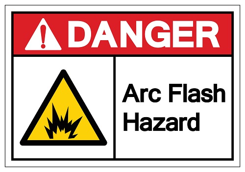
Arc flash labeling is the responsibility of Smith Industries, not the manufacturer or installer of the equipment. Labeling is required for any piece of electrical equipment that may need examination, adjustment, service or maintenance while energized, creating the potential for an arc flash incident to occur.
With the information generated from this entire process, Brian relayed to the Executive Management Team what we had completed, why we needed to do this and had a nice overview of the key points. From that meeting we found out that three quarters of the Smith Industry Plants were in fact out of compliance.
With the realization that this could take a person’s life, the remaining plants initiated their updated study in very short order.
So it is done, we are good for another five years unless we make a significant change in our power distribution study.