
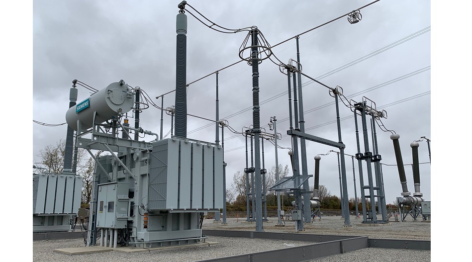
Pictures: Systems With Intelligence Inc.
AUTOMATED THERMAL MONITORING
This article outlines how automated thermal imaging technology can detect some of the most common problems in transformers before they become critical. This allows utilities to plan and schedule repairs, reduce outages and extend the life of their highest value assets.
Introduction
Some of the most common failures on transformers are in the subsystems that are physically located outside the main enclosure or tank of the transformer, making them suitable targets to monitor with infrared sensors. The operation of the transformer is only as good as its worst performing subsystem, therefore monitoring and maintaining the performance of each subsystem is equally important.
The transformer subsystems that are the leading causes of unplanned outages in substations are bushings at 21.6%, on-load tap changers at 29% and the cooling system at 8.7% [1]. From the Canadian Electricity Association report on Forced Outages, these subsystems and components together make up the majority of substation outages.
This article will look at how these subsystems can be better monitored to provide health data and advanced warning of failures to reduce the number of unplanned outages that utilities must deal with.
With this data, utilities can begin to deploy Transformer Intelligent Condition Monitoring (TICM) to strive for “optimal preventive maintenance planning, reduced equipment unavailability and increases in reliability” [2] with their available resources.
Background on Thermal Imaging
Thermal imaging is able to measure the infrared radiation from an object and convert it into a temperature value. An important feature of thermal imaging is that it is ‘non-invasive’. It uses a sensor that can measure temperature values without physically touching the object, therefore it is not required to power down equipment to install the sensor or to make the measurements.
Infrared measurements are affected by many environmental factors including temperature, humidity, wind, distance, and emissivity of the target object.
Some of the most common failures on transformers are in the subsystems that are physically located outside the main enclosure or tank of the transformer.
With these factors in mind, it is difficult to obtain an accurate temperature measurement in an outdoor environment. It is often more meaningful to use comparative measurement; comparing the temperature differences between like components instead of trying to measure an absolute temperature value. A comparative measurement will effectively cancel out the environmental variables.
An advantage in the electric power industry is that the power system runs on three phases, so in many cases inside a substation, it is possible to measure like components on different phases, such as measuring the temperature difference between the A, B and C phase transformer bushings [2]. In this case, instead of trying to calculate what an absolute temperature value should be, it is simpler and more meaningful to compare temperatures between phases. Typically, the temperature of like components should be within 1°C of each other; if not, there could be a load problem or a component problem in the system. The International Electrical Testing Association (NETA) has established a guideline of comparative measurements and relative comparisons to ambient temperature. As outlined in Table 1, NETA has recommendations for actions to take when comparative readings reach defined levels.
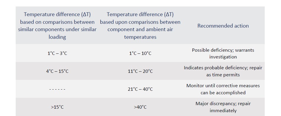
Table 1. Recommended temperature thresholds and actions for monitoring electrical components.
Source: NETA World – Infrared Inspections and Applications
Portable infrared cameras have typically been used by thermographers to periodically inspect substations and other key areas of the grid. While periodic scanning is useful, automated, and continuous thermal monitoring has many advantages such as being able to provide measurements during changing environmental and load conditions, as well as being able to provide the data directly to operators, SCADA, and asset management systems.
Monitoring the On-load Load Tap Changer
with Infrared Sensors
Since the on-load tap changer (OLTC) is one of the highest failure-rate subsystems of the transformer, it is a key subsystem to monitor to ensure it is operating optimally. Some of the more common failure modes in the OLTC produce heat that can be detected by an infrared sensor.
These failure modes are mostly due to the defects in the contacts including alignment problems, wear, pitting and coking.
The effect of these defects is to create reduced surface area between contacts which will cause an increase in temperature due to the I2R factor. Since the infrared sensor is reading the temperature of the OLTC enclosure, an absolute temperature reading would have little value. A temperature threshold may never be reached on a very cold and windy day, or a false alarm may be generated on a very hot day.
To overcome the environmental variables, a comparative measurement should be made between the OLTC enclosure and the main tank of the transformer. If the OLTC enclosure ever exceeds the temperature of the main tank, then there is some localized heating taking place. If the defect is only in one phase, then the localized heating may be evident in that section of the OLTC enclosure.
While periodic scanning is useful, automated and continuous thermal monitoring is able to provide measurements during changing environmental and load conditions, as well as to provide the data directly to operators, SCADA, and asset management systems.
The problem may exist at only one OLTC setting if only one set of contacts is defective. Possibly an overload condition caused current to flow beyond the rated capacity of the contacts and caused pitting on that set of contacts. This means excessive heat will be generated only when the OLTC is in that position. It can then be determined which contacts are damaged by correlating the rise in temperature delta with the switch position.
It may also be the case that heat problems are detected at a particular time of the day. This could indicate a problem with the contacts that only shows up under heavy load. The I2R factor will produce more heat in the contacts when there is high current flow, a problem that may not be revealed by periodic thermal scanning.
Depending on the conditions, the overheating problems in the OLTC may be transient, only occurring under specific conditions or on a particular set of contact points. Due to the transient nature, periodic infrared inspection may miss the problem where an automated, full-time monitoring system will find it. Additionally, an automated system will collect and store temperature data, allowing it to be trended and correlated with weather and load current to further narrow down the problem. OLTC temperature data can also be correlated with the tap position to help isolate which contact points require maintenance.
A single thermal and visual sensor can be used to monitor hundreds of points in a substation when set to automatically patrol a site
The Cooling System
Proper operation of the cooling system is critical for optimal operation of the transformer and preservation of its life expectancy. An overheating transformer can damage the winding insulation, causing shorts and possible catastrophic failure. Monitoring of the cooling system ensures that all its components are correctly functioning and the transformer is operating within its designed temperature ratings.
Using infrared temperature monitoring allows several cooling system components to be monitored using a single sensor. The infrared sensor detects the heated oil as it enters the top of the radiators and cooling oil as it flows down. This pattern will show the oil being cooled as it moves through the system when it is operating correctly. Deviations between radiators can indicate several issues such as failing pumps, blocked radiators, coolant level problems, or leaks.
Comparative thermal measurement can be done between like radiators to determine that they are operating correctly.
Using infrared temperature monitoring allows several cooling system components to be monitored using a single sensor.
Comparative measurement can also be done between the top and bottom of the radiator to determine the cooling delta that is being provided. Coolant level in the conservator can also be monitored.
Cooling fans are an integral part of the system and are required to provide air flow through the radiators to dissipate heat from the coolant. As the fans operate, the motors will generate a heat pattern that can be monitored by the infrared sensor. Comparative measurements can be made between cooling fans to ensure they are operating at the same temperature. Fan motor temperature measurements should also be correlated with the fan control signals to ensure they are operating when they are supposed to be and are not overheating due to worn bearings, etc.
Transformer Bushings
Bushings are among the most common subsystems on the transformer that fail. Many bushing tests, measurement or monitoring techniques require an outage to perform the test or to install the test equipment. Infrared sensors can monitor bushing temperatures without a physical connection making it an easier and more economical method to continuously monitor many points without the high cost of installation.
Before failure, it is likely that the bushing will develop excessive heat that can be detected using an infrared sensor.
The most common deficiencies that are detected with infrared sensors are due to insulation degradation causing arcing or a mechanical connection problem with an I2R fault.
As with most situations it is recommended to use comparative measurement between the bushings to eliminate the environmental effects on the temperature reading.
Any temperature difference of more than 4°C is an indication of a problem that requires repair [2]. Alarms should be set in the monitoring system to alert operators of the condition so maintenance can be scheduled.
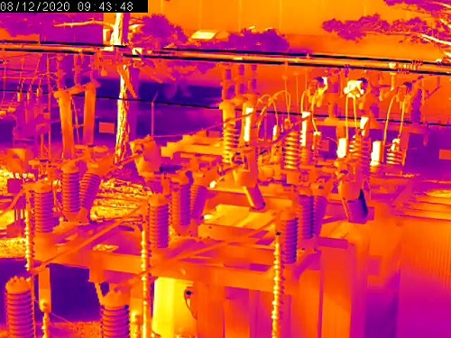
Snapshot from a thermal sensor shows a visual representation of asset temperatures
Infrared sensors can monitor bushing temperatures without a physical connection making it an easier and more economical method to continuously monitor many points without the high cost of installation
Monitoring the Main Tank
The infrared sensor will only be capable of monitoring the outer wall of the main tank; however, there is still valuable information that can be obtained, especially when correlated with other data. As it has been stated, an accurate absolute temperature is difficult to obtain in an outdoor environment; however, the temperature pattern and rate of change can be an indication of problems in the transformer windings. If temperatures of the transformer tank are increasing under the same weather and load conditions, it may be an indication of internal arcing. This may also be indicated by a hot spot in localized area of the tank since arcing occurs at a very high temperature.
Other Equipment
There are many other pieces of equipment around the transformer that should also be monitored with thermal imaging including arrestors, CTs, VTs, breakers, disconnect switches, etc., as these devices have insulation and connection points that can degrade and become an issue in the substation.
Processing the Data
Automated thermal systems collect data continuously, providing a wealth of information to the utility. Systems with built-in analytics can raise alarms as soon as out of tolerance condition is reached, providing the utility an opportunity to correct the problem before a failure occurs.
Additionally, the data can be stored and exported to other systems such as SCADA or asset management. Machine learning systems can analyze and detect anomalies from thermal data and images, correlated with other data such as weather, time of day and electrical load.
Machine learning can go into much further detail and enable more accurate detection of faults in transformer components than manual data interpretation.
Summary
Advancements in infrared technology and the communications around it make thermal monitoring more widely available through reduced cost, ease of use and accessibility to the data. Automated thermal inspections can be used for more than just finding hotspots in the electrical system. With advanced analytics correlated with external information such as load and environmental conditions, thermal sensors can isolate and help utilities pinpoint the most common transformer problems before failures occur.
Advancements in infrared technology and the communications around it make thermal monitoring more widely available through reduced cost, ease of use and accessibility to the data.
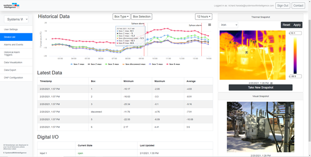
Thermal monitoring dashboard
An automated, online monitoring system improves the safety of utility operations by reducing operator exposure to hazardous environments while reducing maintenance costs and unplanned outages through deployment of Condition Based Maintenance (CBM), or the more focussed Transformer Intelligent Condition Monitoring.
References
-
Canadian Electricity Association, Forced Outages Report
-
Cigre Working Group A2.44 – Guide on Transformer Intelligent Condition Monitoring (TICM) Systems
-
Don A. Genutis, Netaworld, Infrared Inspections and Applications, 2006
-
Wernsing and A. Rothweiler, “Data Enables Proactive Asset Management,” T&D World Magazine, 2015