
Pictures: Doble Engineering Inc., Shutterstock
SPECIAL TRANSFORMER TEMPERATURE RISE TESTING
The split-winding arrangement in core-form power transformers requires special thermal design considerations. Presently, industry standards do not provide significant detail on the temperature rise test for these unique arrangements. This paper will demonstrate how to supplement the industry standards for this special transformer construction and some common problems that arise in practice.
Introduction
In core-form transformers with a concentric winding arrangement, two or more separate winding sections may be situated one above the other (axially). This unique arrangement is commonly referred to as “axial split-windings” or “axially-stacked windings”. The split-winding arrangement is most commonly used in three-winding rectifier transformers and three-winding unit auxiliary transformers (UAT).
Three-winding transformers with axial split-windings are unique because the two axial sections are normally associated with two different terminals. Therefore, unique combinations of varying voltage, impedance and active power can be present, which requires special consideration.
In addition to the various possible terminal characteristics described above; there exists a fundamental difference in the temperature rise distribution model when compared to the traditional full-axial height winding arrangement because the relative top-oil, average-oil and bottom-oil temperature rises are not the same for all windings.
It is therefore necessary to understand the differences in the two temperature rise distribution models and then be able to refine the relative oil temperature rises for each winding in order to appropriately determine the average winding temperature rise and winding hottest-spot temperature rise for each winding.
Presently, industry standards do not explain the modifications that are needed to the temperature rise test for these special winding arrangements. This paper will demonstrate how to supplement the industry standards for this unique transformer construction and some common problems that arise in practice.
An application for the axial split-winding arrangement may be to serve large unit auxiliary loads within one three-winding transformer at a generation plant, as opposed to using two separate two-winding transformers.
Winding Arrangement
The traditional and most common winding arrangement for core-form transformers includes an arrangement in which the windings are approximately the same height and are arranged concentrically over one another (radially). Figure 1 depicts the traditional transformer winding arrangement for a three-winding transformer with the primary (designated as “HV”) placed concentrically in-between two secondary windings, “XV” and “YV”. The axial split-winding arrangement includes two or more separate winding sections that are situated one above the other axially. An application for the axial split-winding arrangement may be to serve large unit auxiliary loads within one three-winding transformer at a generation plant, as opposed to using two separate two-winding transformers. The application could allow interconnection of two separate auxiliary buses and possibly with secondary voltages and active power ratings at different levels [1]. Figure 2 depicts an axial split-winding arrangement with one set of secondary windings designated as “YV” placed axially above the other set of secondary “XV” windings.
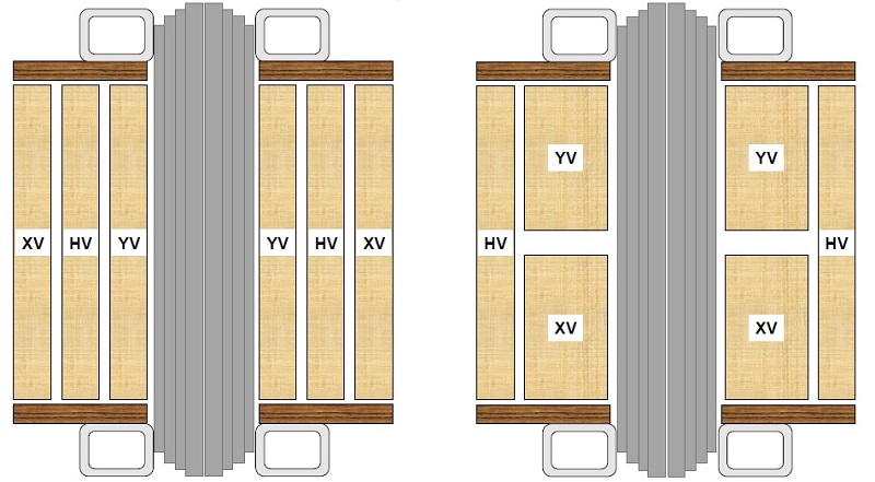
Figure 1. (left) Traditional transformer winding arrangement Figure 2. (right) Axial split-winding transformer winding arrangement
The importance in noting the difference between the axial split-winding arrangement and the traditional concentric winding arrangement is that the transformer temperature rise distribution is appreciably different between the two arrangements, and therefore greater attention is required in determining the oil temperatures. Namely, in the axial split-winding winding arrangement, the “YV” winding from Figure 2 should not use the average-oil temperature rise of the tank oil, rather it is necessary to determine the average-oil temperature rise for the “YV” winding separately from the tank average-oil rise.
Transformer Temperature Rise Distribution
In the traditional transformer temperature rise distribution model, the winding heights are assumed to be uniformly distributed within the transformer core window. This assumption yields additional assumptions such as the top-oil temperature rise is adjacent to the top of the windings and, similarly, the bottom-oil temperature rise is adjacent to the bottom of the windings. In other words, the temperature rise of the oil inside the windings is assumed to increase linearly with the height of the windings. Additionally, the heat generated from the windings, in the form of losses, is assumed to transfer (on average) to the adjacent oil in proportion to the corresponding winding height. In graphical form, these assumptions result in two parallel lines, with one representing the winding temperature rise relative to height and the other representing the oil temperature rise relative to height. The difference between the two parallel lines is the temperature drop between the winding and the adjacent oil, which is commonly referred to as the average winding gradient.
In the traditional transformer temperature rise distribution model, the average-oil temperature rise (Figure 3 – Point B) is determined by the arithmetic mean of the top-oil temperature rise (Figure 3 – Point A) and bottom-oil temperature rise (Figure 3 – Point C). Also, in the traditional model, the average winding temperature rise (Figure 3 – Point B’) is the sum of the average-oil temperature rise and the average winding gradient. Point K in Figure 3 is the winding hottest-spot (“hotspot”) temperature rise and is determined by the sum of the top-oil temperature rise and hotspot gradient, which is determined by a hotspot factor and the average winding gradient. The hotspot factor is a dimensionless quantity greater than 1.0 and is individually assigned to each winding based on a combination of mathematical analysis and empirical test results from direct measurement [2] .
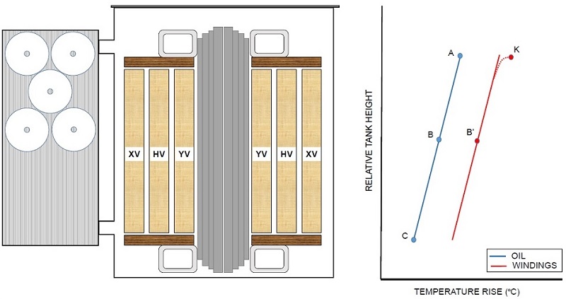
Figure 3. Traditional transformer temperature rise distribution model
This stable reference temperature for each axial split-winding should follow the method for determining the oil temperature rises according to the axial split-winding temperature rise distribution model.
A figure similar to Figure 3 can be found in International Standard IEC 60076-2 [3].
The IEC standard uses similar points to help illustrate the terms for bottom-oil, average-oil, and top-oil temperature rise; however, it defines the vertical axis of the chart as “Winding Height (%).”
Although the IEC standard associates the 0%, 50%, and 100% of the winding height with the location of the bottom-oil temperature rise, average-oil temperature rise, and top-oil temperature rise of the tank (respectively), the differentiation in the vertical axis is useful for the axial split-winding transformer temperature rise distribution model.
In the axial split-winding transformer temperature rise distribution model, one of the main differences is the oil temperature rise to be used to determine the average winding rise. It should not use the average-oil temperature rise (Figure 4 – Point B) of the tank oil, rather it is required to determine the average-oil temperature rise across the “YV” winding, which is Point D in Figure 4. Point D is the arithmetic mean of the oil rises from points A and B of Figure 4.
Figure 4. Axial split-winding temperature rise distribution model for YV winding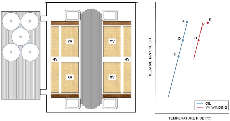
The “XV” winding in Figure 4 will require similar adjustments to the temperature rise distribution model. The “HV” winding in Figure 4 uses the traditional temperature rise distribution model because the windings are not stacked axially and are full height.
Corrections to the Temperature Rise Test
The purpose of the temperature rise test is to establish the top-oil temperature rise, average winding temperature rises, and winding hottest-spot temperature rises. The temperature rise test is primarily composed of four components. The first component is the cold-resistance measurements of the windings. Next is the total loss injection for determination of oil temperature rise. Special attention is given to each component of the temperature rise test for transformers with axial split-windings, but this paper will focus on the cold-resistance measurements and total loss injection because the principles described can easily be applied to the other two remaining components.
Cold-Resistance Measurements
The industry standards have very definite criteria to minimize recording errors in the cold-resistance measurement [4]. One of the major prerequisites is the determination of the cold winding temperature since resistance varies proportionately with temperature. Cold resistance measurements require the windings and oil temperature to be stable. This stable reference temperature for each axial split-winding should follow the method for determining the oil temperature rises according to the axial split-winding temperature rise distribution model.
Total-Loss Injection
The most common method for temperature rise testing power transformers is to utilize the short-circuit method, whereby the load is simulated by the effect of short-circuit current. In the case of total-loss injection, the primary goal is to simulate and sustain total-losses on the transformer that coincide with previously measured no-load and load losses for a given active power rating for the purpose of determining the steady-state oil temperature rises.
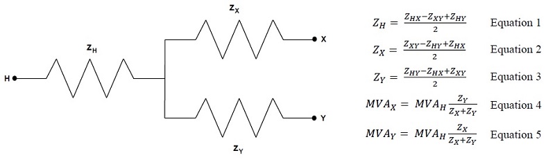
One difficulty that can occur during the total-loss injection for three-winding transformers, which may also be prevalent during the rated winding-current injection portion of the temperature rise test, is that differences in impedances and active power ratings can result in under-loading or over-loading of certain terminals under test. Figure 5 helps illustrate the equivalent three-winding impedance network and can be derived from Equations 1 through 3. Equation 4 and Equation 5 can be used to solve for the load-current division if both the “XV” and “YV” terminals were shorted during the short-circuit method of the temperature rise test (i.e. a short across point “X” and point “Y” in Figure 5).
Figure 5. Equivalent three-winding impedance network
This can present difficulties in achieving total-loss injection because the over-loading of one set of terminals may be significant and result in exceeding recommended temperature rise limits or current ratings of ancillary equipment. Therefore, it is recommended that the details of the temperature rise test for transformers that fall within this scenario be presented and agreed to during the tender stage. The transformer manufacturer may present recommendations to inject less than 100% of the total-losses and then apply corrections to the oil temperature rises as outlined in the industry standards [3], [4]. It should be noted that the industry standards typically have a minimum percentage of the total-losses for which the temperature correction equations are valid. Due to the transformer impedance requirements or active power ratings, it is possible that the required total-losses fall outside of the minimum percentage as indicated in the industry standard.
Alternatively, it may be of interest to the end user to meet and not deviate from the industry standards. Therefore, it may be recommended to have the transformer manufacturer design the transformer windings and ancillary equipment to withstand any resulting over-loads, which result from maintaining at least the minimum percentage of the total-losses as indicated in the industry standards. It should be noted that the industry standards also have upper ranges for the percentage of total-losses and rated winding current for which oil temperature rise correction calculations can be made; however, the IEEE and IEC standards are not in agreement in regard to the allowable ranges.
Due to the transformer impedance requirements or active power ratings, it is possible that the required total-losses fall outside of the minimum percentage as indicated in the industry standard.
There are additional considerations that may need to be considered in determining the required total-loss for unique three-winding transformers such as axial split-winding transformers. The derivation of the load-current division from Equation 4 and Equation 5 and the use of the measured impedances and losses for each two-winding combination can result in some inaccuracies in large transformers where eddy losses in windings and stray flux losses in structural components are considerable. Additional corrections to determine the three-winding (combined) total-losses may be useful and required [5].
After the top-oil temperature rise has stabilized during the total-loss injection, according to the requirements in industry standards, then the short-circuit current should be reduced to the rated winding currents. The instant where the total-loss injection transitions to the rated winding-current injection is commonly referred to as “cutback.” The oil temperatures should be recorded for the total-loss injection immediately before the cutback. The recorded oil temperatures should be categorized according to the axial split-winding temperature rise distribution model for windings that are axially-stacked. These categorized oil temperature rises, from the moment of cutback, will be used to determine the final average winding temperature rises and winding hottest-spot temperature rises after rated winding-current injection and hot-resistance measurements are completed.
Other Special Thermal Considerations
The axial split-winding example presented in this paper illustrated two axially-stacked sections divided into two equal height winding segments. In practice, other winding constructions are possible, such as two unequal height winding segments due to differences in voltage or impedance requirements. Unequal height winding segments present additional challenges in determining the bottom-oil, average-oil, and top-oil temperature rises for each axially-stacked winding.
It may also be advisable to install temporary or permanent temperature measurement probes at the winding heights that coincide with the tank oil adjacent to the bottom, middle, and/or top of the axial split-windings. Additionally, a different temperature rise calculation method can be applied based on the proposed winding heights of each axial split-winding.
It is possible that one of the axial split-windings will be under-loaded while the other over-loaded during temperature rise testing.
If direct measurement is used to determine the winding hottest-spot temperature rise during the temperature rise test, and there exists unequal loading of the axial split-windings, then the direct measurement may not result in meaningful winding hottest-spot temperature rises at rated load for all of the windings. It should be noted that this scenario exists due to the short-circuit temperature rise test method; however, it is not a limitation that necessarily exists in operation. For reasons already explained in this paper, it is possible that one of the axial split-windings will be under-loaded while the other over-loaded during temperature rise testing, which means that a more refined calculation may be necessary to determine the calculated winding hottest-spot temperature rise from the direct temperature measurements.
Due to the difficulty in obtaining a correct measurement at full load and total-losses, it may not be advisable to use the direct measurement to guarantee the winding hottest-spot temperature rise. Another option may be to determine the hotspot factor from the direct temperature measurement [2] for each axial split-winding at the presumed loading based on the load-current division as determined from Equation 4 and Equation 5. Once the hotspot factor is determined for the applied test current then the temperature corrections based on the industry standards can be applied to the oil temperature rises and winding temperature rises. The hotspot factor can then be applied to the corrected winding gradient and then added to the top-oil temperature rise for each axial split-winding. When determining the hotspot factor, it may be necessary to review the variation in the hotspot factor at different percentages of rated load [6].
Conclusion
Transformers with split axial-windings present unique challenges when performing temperature rise testing. The industry standards generally have enough provisions to determine the oil and winding temperature rises for split axial-windings if some discretion is used in applying various corrections as presented in this paper. This paper provided some considerations for the temperature rise distribution model and temperature rise test via the short-circuit method. This paper emphasizes the necessity to consider transformers with axial split-windings as a unique design, which requires special involvement between the buyer and transformer manufacturer during the tender stage.
References
-
IEEE Guide C57.116, IEEE Guide for Transformers Directly Connected to Generators, IEEE, 3 Park Avenue, New York, NY 10016, USA
-
IEEE Standard 1538, IEEE Guide for Determination of Maximum Winding Temperature Rise in Liquid-Filled Transformers, IEEE, 3 Park Avenue, New York, NY 10016, USA
-
IEC 60076-2, Power transformers - Part 2: Temperature rise for liquid-immersed transformers, International Electrotechnical Commission, 3, rue de Varembé, PO Box 131, CH-1211 Geneva 20, Switzerland
-
IEEE Standard C57.12.90, IEEE Standard Test Code for Liquid-Immersed Distribution, Power, and Regulating Transformers, IEEE, 3 Park Avenue, New York, NY 10016, USA
-
IEC 60076-8, Power transformers - Part 8: Application guide, International Electrotechnical Commission, 3, rue de Varembé, PO Box 131, CH-1211 Geneva 20, Switzerland
-
H. Nordman and O. Takala, “Transformer Loadability Based on Directly Measured Hot-Spot Temperature and Loss and Load Current Correction Exponents,” CIGRE Report No. A2_307-2010