
ONLINE BUSHING MONITORING
Bushings are crucial components for large power transformers, being the termination points and physical electrical connections to the high and low voltage grid. Regular testing is of utmost importance since bushings account for 5% to 50% of transformer faults, but how are we to know which tests should be carried out in order to optimize time and budget?
Introduction
Bushings are crucial components for large power transformers, being the termination points and physical electrical connections to the high and low voltage grid. There are different designs and technologies, however, failures in those components can cause unplanned outages, huge direct and indirect financial losses and, in some cases, catastrophic consequences involving fire and explosions. Regular testing is of utmost importance since bushings account for 5% to 50% of transformer faults, depending on design and application [1].
There is a variety of offline measurements that can be carried out in the field to check the insulation condition at a particular point in time [1-5], such as: Dielectric Frequency Response (DFR) [2], Power Factor (PF) Tip-up, Power Factor at different temperatures, Dissolved Gas Analysis (DGA), oil quality, DC insulation test, and Partial Discharges (PD). However, all of them required the transformer to be de-energized, as well as significant time and skills are needed to carry out a meaningful diagnosis. Due to time constraints and difficulties in interpretation, the most common tests that are typically performed are the Capacitance and Power Factor (a.k.a. Tan Delta or Dissipation Factor) test, done at just one temperature at the moment of testing, voltage and frequency.
These tests can assess and highlight an advanced stage of degradation like short circuits across internal control layers or a bulk degradation of the oil/paper insulation due to severe contamination.
However, there are also faults and level of degradations that cannot be easily detected in this way [5-7]. Indeed, there are many different possible failure modes [1,8] such as: insulation ageing, moisture contamination, crack in porcelain, oil leakages, broken or loose connections, particle contamination, contamination in either the internal or external surface of the porcelain, presence of local amount of moisture, electrical surface tracking phenomena, internal PD and arcing.
In order to identify those failure modes and save a bushing before the degradation is at an advanced stage it would be required to choose the most appropriate offline tests, or a combination of multiple tests, thus investing quite a significant amount of time.
But how are we to know which tests should be carried out in order to optimize time and budget?
Monitoring bushings on-line, under real operating conditions, offers a solution to identifying different failure modes and saving a bushing before the degradation is at an advanced stage.
A solution is represented by monitoring the bushings on-line, under real operating conditions. Historically, this is done by collecting the 50/60 Hz leakage current at the test (or voltage) tap (Figure 1) and then comparing the currents in each bushing to check for anomalies in one bushing current in terms of either amplitude or angle [7].
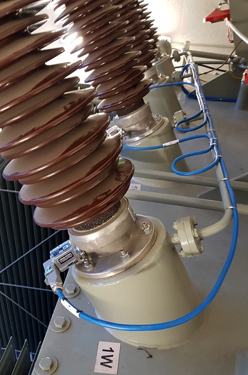
Figure 1. Bushing adaptor installed at the test tap for PD and Leakage Current online monitoring
Modern devices can do something more, by extending the frequency range of the sensor and acquisition system within the MHz range in order to detect another important parameter: Partial Discharges (PD). However, this technology is not widespread and is rarely requested as a mandatory requirement from end-users. Why?
Because there are mainly two barriers:
-
Difficulties in Partial Discharge interpretation
-
Concerns with PD detection capabilities
The first item is quite reasonable since it is true that the understanding and interpretation of Partial Discharges require experience and skills. However, if the monitoring system is properly designed, acquiring data in a meaningful format and removing most of the noise and disturbances, it is then possible to use algorithms and simple graphical tools to make the information more accessible to the end-user. Also, PD monitoring suppliers can make their experience available to the end-user, sharing and transferring knowledge and helping in building trust in this technique [6].
The second item is driven by a general misconception, where the typical thinking is that “accurate PD measurements are very difficult to perform on site and with the bushing installed on the transformer” or that “due to high level of noise online PD detector cannot reach the same sensitivity (in pico-Coulombs) required during the factory offline tests”.
Hence the typical questions such as “How many pico-Coulombs can you detect? What is your monitoring system sensitivity? At how many pC shall I switch the transformer off?”. This is an example of confusion, and at times obfuscation, when it comes to PD and its application to power transformers.
End users care about the transformer and its condition. The science and art of PD measurement can be a distraction if not applied correctly. Does a transformer owner really care about the nuances of pico-Coulombs specification on a 20-year-old transformer? Likely not! Rather than focusing on pico-Coulomb measurements, focus on the failure modes your PD monitors detects. That way the focus is on the real issues and the failure modes your monitor can reliably detect. That must always be the priority.
In fact, by analyzing the shape and characteristics of the PD [9-10] and its changes over time, together with the other monitored parameters like load, temperature, and leakage current, it is possible to better describe the degradation phenomenon, identify the possible failure mode, and enable a more effective maintenance planning program.
Principles and requirements for effective online Partial Discharge monitoring in bushings
PD measurements are generally carried out in the factory during the acceptance tests (FAT), in an environment that is arranged to be free from electrical noise, thus achieving a detection sensitivity able to detect very small discharges in the range of a few pico-Coulombs (<5 pC). Due to the normally high amount of noise in the field and the difficulty of interpreting the PD results, this diagnostic parameter is rarely considered in permanent monitoring systems. The general view of it is that online sensitivity is too poor to detect less than 5 pC.
The purpose of online monitoring is neither to replace, nor exactly replicate the factory acceptance tests or offline measurements. Instead, its purpose is to detect anomalies in real operating conditions that could not be identified otherwise and, therefore, to identify the most suitable test for the final confirmation and action.
To achieve this purpose, it is therefore not necessary to use systems capable of detecting a few pC and in total absence of noise. Rather the key is in detecting, in a reliable way, discharges caused by defects originated during the operating life of the transformer, i.e., after decades of thermal, electrical, and mechanical stress, like disconnection of equipotential connections, generation of large voids and cracks in the insulation, short circuits between multiple layers and many others. In fact, it should be considered that the bushings that are 10, 20 or 30 years old will have an aged oil, with the possible presence of humidity, particles of various kinds, sludge and residues. Also, the cellulose will have different mechanical and chemical characteristics, potentially weakened by the presence of water or excessive thermal heating.
The condition and chemical/mechanical characteristics of bushings that have been in service for decades is very different from the condition at the time of the FAT, resulting in unique situations regarding PD measurements.
The condition and chemical/mechanical characteristics of bushings that have been in service for decades is very different from the condition at the time of the FAT, resulting in unique situations when it comes to PD measurements.
The same identical defect could generate discharges of different intensity depending on the age of the surrounding insulation, the operating temperature, the oil breakdown voltage, the presence of particles in oil, the cellulose mechanical strength and many other factors linked with the normal bushing ageing in the field.
Therefore, the key is not to focus on the pico-Coulomb detection, but rather on the failure mode, correlating PD phenomena together with variations in temperature, load, capacitance and power factor under real operating conditions.
Are all the PD detectors and monitors suitable for online PD detection in real operating conditions? No, they are not. Adapting a standard portable unit or offline kit for online purposes might not work. The online monitoring system should be properly designed considering transformer and bushing application, thus following a number of solid principles and requirements:
Principle #1: Capabilities of acquiring PD continuously, thus not scheduling several measurements per day
Acquisition gaps are not allowed. This is very important to detect arcing event happening during a short circuit between layers or due to floating shields/connections that accumulate charge and sudden discharges. By making only a set number of acquisitions per day there is very high probability of missing such events [6, 11].
Principle #2: Capabilities of automatically removing noise and disturbances, and also removing the cross coupling from the other phases
This is important because these interferences can overlap to the actual PD and affect the evaluation of amplitude and repetition rate, i.e. PD intensity and its trending over time. Figure 2 shows an example of a PD acquisition in three phases. Each phase has a PRPD pattern, but the defect is actually generated from Phase B only. Without the automatic denoising logic, the system would record and keep pulses in each phase (Figure 2, top), instead of focusing on where the actual PD source is (Figure 2, bottom) and this would affect the statistical amplitude and repetition rate evaluation. Furthermore, it would make the pattern analysis difficult, relaying on experts to help in understanding if that PD is an actual PD or a cross-coupling event.
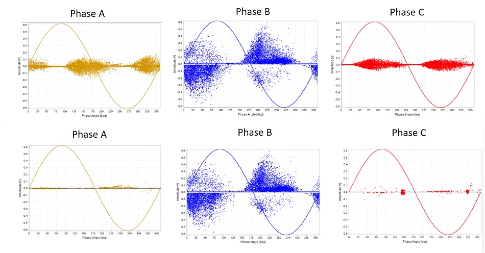
Figure 2. Differences between an acquisition with (bottom) and without (top) an automatic de-nosing and cross coupling rejection logic.
Principle #3: Capabilities of separating the PD in the bushings from those in the main tank
There are several elements to be considered that can allow the conception of an intelligent algorithm capable to discriminate if the recorded PD activity is inside the bushing or not. One of the most known elements, as an example, relates to the ability of analyzing the PD pulse polarity with respect to the applied voltage. Indeed, the PD pulses coming from the main tank have opposite polarity from those coming from the bushing condenser core when detected by an impedance installed between the test tap pin and ground. This is quite complex but can be summarized by the difference between having the measuring impedance in either "direct" or “indirect” circuit within the Equipment Under Test (EUT).
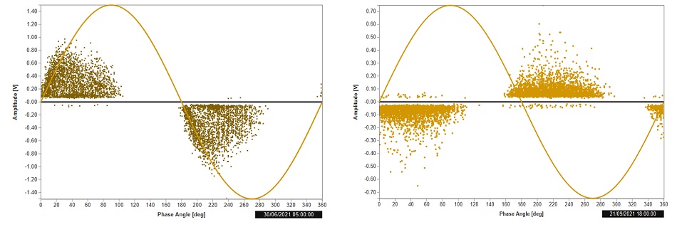
Figure 3. PRPD pattern of a PD acquired in the bushing (left) against a PD on the top of the winding (right). They have opposite polarity under the same sinewave.
Principle #4: Capabilities of synchronizing the PD pulses with the true voltage applied at the bushing
The position of the PD pulses with respect to the zero crossing of the applied voltage is very important to understand the source of PD and its degradation stage [12-13]. Few degrees of differences can make a huge difference in the diagnosis. For that reason, the synchronization voltage must be accurate and be recorded from the test tap together with the high frequency pulses, i.e. not from external power supply sources in the substation to which a manual phase shift has then to be applied.
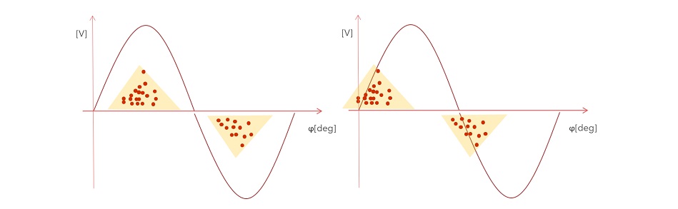
Figure 4. The same PRPD pattern could show a very early (left) or quite advanced (right) stage of degradation depending on its position with respect to the zero crossing of the applied voltage, which must be very accurate and acquired from the bushing tap together with the PD.
Principle #5: Capabilities of using an extended full scale to detect arcing events
PD instruments used for factory acceptance tests or periodic measurements might have too small of a full scale, mainly focused on detecting small PD activities with a few pC. For reliable online monitoring application, it must be different, focusing also on the large events that can be many orders of magnitude larger, in the range of hundreds of nano-Coulombs. This has been shown previously as crucial whenever there is a floating object [11] or an arcing event between layers [6]. In terms of Volts, with a typical bandwidth of 20-30 MHz, the full scale must at least be equal to 20 Volts peak-to peak.
Success Story #1:
130 kV OIP bushing contamination during manufacturing
A batch of 130 kV OIP bushings manufactured in 2016 was installed in a fleet of new transformers in North America. After about a year, an alarm was notified by the monitoring system for increased power factor in two bushings.
Figure 5 shows the increasing trend of the relative Power Factor, estimated from the variation of the angles of the currents (red trend line). The estimated Power Factor started to rise in March and reached a relative value (incremental change to be added algebraically to the nominal value) of 0.7%, thus justifying a further investigation.
It is interesting to note the black trend line, showing the number of Partial Discharges per second detected in the same bushing (X3).
After some sporadic events during the months of October and November, the PD activity was quiet, occurring intermittently until April, when it started again with more frequency, together with an increase of the Power Factor, until the transformer was de-energized.
Looking at the Phase-Resolved Partial Discharge (PRPD) pattern, provided every hour by the monitoring system, we can recognize how the PD activity has grown over time and how the PD polarity is "direct", which means positive under the positive sinewave, i.e. inside the bushing. The shape of the pattern also recalls studies published on PD in oil in presence of metal particles [14].
By adding the online Partial Discharges analysis to the relative variations of leakage current in transformer bushings it is possible to find out correlation patterns that enable failure mode identification and better planning of offline tests and maintenance.
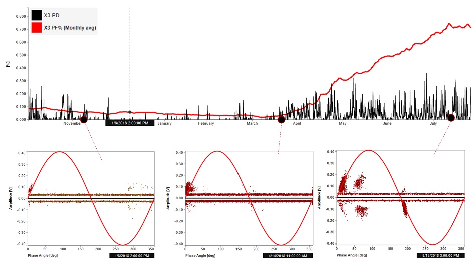 Figure 5. Increase of Power Factor (red trend line) in X3 bushing correlated with PD occurrence increase in the same bushing (black track)
Analyzing and correlating both the PD and the Power Factor, it was speculated there was a possible contamination of metallic material. It was suggested to carry out a DGA measurement, to confirm presence of PD, plus an oil quality measurement.
Table 1 shows the results of the oil analysis, with exceptionally high levels of hydrogen and with abnormal BDV and Tan Delta, confirming not only the presence of PD, but also a significant reduction in dielectric strength, both probably due to the metal contaminants.
 Table 1. Oil analysis results
It was therefore decided to inspect the bushing and a significant amount of aluminum particles and carbon deposits were found, confirming the assumptions made and the on-line analysis of the monitoring system.
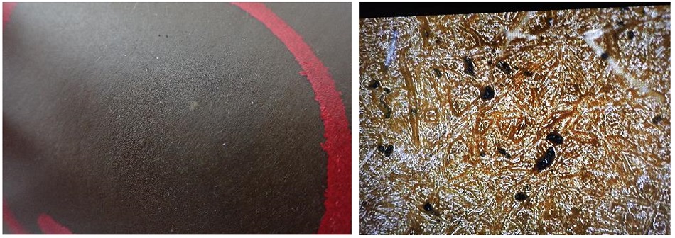
Figure 6. Metallic particles on the surface of the C1 core and in paper samples during microscopic analysis
The bushing was replaced but at the same time a DGA measurement was planned for all the bushings from the batch (which had no monitoring system), which found two additional bushings were in a similar condition.
According to the asset manager:
-
The monitoring system was mainly installed to monitor the main transformer tank and no problems were expected on bushings, especially considering they were new.
-
By implementing a standard program of electrical testing every six years, it would not have been possible to detect the problem in time and prevent a possible unexpected failure.
-
Thanks to the monitoring system, three new bushings were saved. A failure might have possibly been catastrophic.
Success Story #2:
110 kV RIP bushing short circuit between internal control layers
Although the resin insulated bushings are considered to be less prone to PD activities by design, due to a specific manufacturing process that avoids the presence of vacuoles in the solid insulation, it is certainly possible that these bushings, after a certain amount of time in service or even prematurely, due to problems during transport and installation, show defects that can generate Partial Discharges. Unlike OIP bushings, the solid insulation system does not tolerate PD activities and in presence of PD it can quickly deteriorate, creating a conductive channel between the control layers.
The case depicted here describes a 110 kV RIP wall-mounted bushing (Figure 7), monitored by the same type of system used in the previous cases.
After about two years the system gave an alarm for a sudden relative capacitance increase of about 14% in bushing K. The bushing was taken out of service and tested offline, confirming the increase detected by the monitoring system (Figure 8).
From the retrospective analysis of the data recorded by the monitoring system, it was possible to find some discharge activities in the same bushing about one month before the capacity increase (Figure 9).
The PD at that time was small, at inception stage, and with not enough intensity to warrant an alarm. However, they were already showing a typical PRPD pattern for cavities in resin [15].
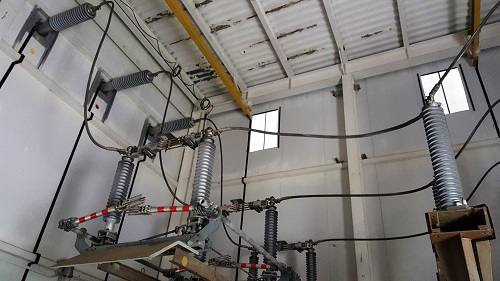
Figure 7. RIP bushings, wall-mounted
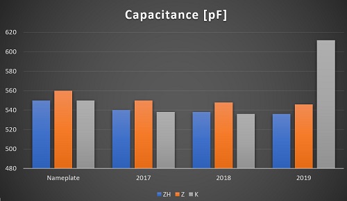
Figure 8. Results of offline Capacitance measurements over the years. Bushing K shows a Capacitance increase ranging between 14% and 15%
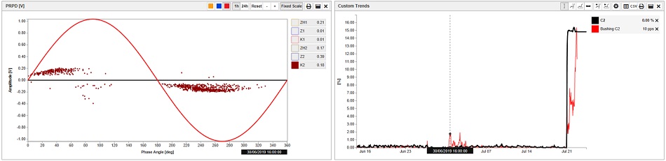
Figure 9. PRPD pattern recorded 20 days before the Capacitance increase
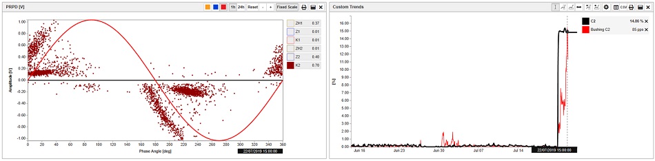
Figure 10. PRPD pattern right after the Capacitance increase (same full scale as Figure 9)
The discharges remained active for no more than two days and then disappeared completely until the increase in capacitance, during which they were active again but, this time, increasing in both amplitude and repetition rate, as shown in Figure 10.
From this experience it was decided to consider new alarm thresholds for PD activities in RIP bushings, as this case clearly indicated PD could be an important precursor of possible short circuits between the bushing control layers, thus allowing preventive and planned actions well in advance.
It should also be considered that in the absence of oil, and, therefore, of possible feedback given by DGA laboratory test, the Partial Discharge analysis acquired even greater importance in the context of RIP bushings, as a valid confirmation method whenever there is a correlation with the variations of the leakage current.
Failure mode analysis enhanced by online PD analysis
Table 2 shows a very simple summary of the influence and effectiveness of online PD monitoring during the diagnostic process in a number of real cases.
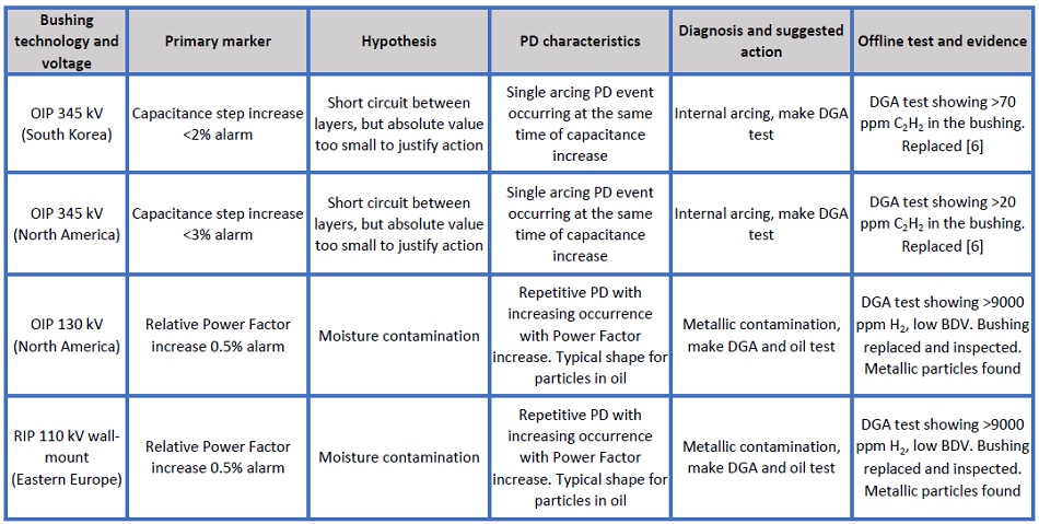
Table 2. Influence and effectiveness of online PD monitoring during the diagnostic process in a number of real cases
Conclusions
By adding the online Partial Discharges analysis to the relative variations of leakage current in transformer bushings it is possible to find out correlation patterns that enable failure mode identification and better planning of offline tests and maintenance.
In the cases reported in this article, it was possible to see how the PD analysis has helped to detect several different failure modes – internal arcing between control layers in OIP bushings [TT1]; presence of metal particle-type contaminants in OIP bushings; and internal PD and control layer short-circuits in RIP bushings.
It must be pointed out that the PD system must be designed in a proper way to be effective and easy to interpret, i.e. following five important requirements:
-
Continuously monitor PD
-
Remove noise and cross-coupling automatically
-
Discriminate whether the PD is in the main tank or in the bushing
-
Detect arcing events with an extended amplitude range
-
Get the synch reference signal from each bushing
-
Provide at least one PRPD pattern per hour and trend with other parameters such as load, temperature, and leakage current
Particular attention should be paid to RIP bushings. Although they have much better PD characteristics if compared with RBP and OIP bushings, they can still be affected by defects after installation (due to bad storage or external events such us through-faults or over voltages) that can precipitate PDs. Different from paper-oil technology, the epoxy resin cannot withstand PDs, which can quickly evolve into a short circuit between internal layers. While the DGA test of the bushing’s oil represents a valid technique to confirm the occurrence of an arcing between layers, it does not apply to RIP bushings due to the absence of oil. But case #2 shows that PD online can be an equally valid alternative to confirm or prevent failures in the RIP bushings, especially if correlated with capacitance changes.
Acknowledgments
Many thanks to industry experts, friends and end-users for their contribution on this subject, with special thanks to Colin Clark from Altalink (Canada) and Claudio Angelo Serafino from Terna (Italy).