
SPECIFICATION TIPS
Authored by:
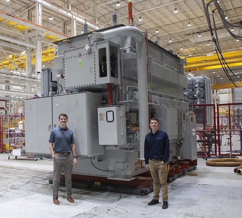
 Charlie Bowman
 Curtus Duff
Because no rules exist, one thing to remember is that the perfect specification is the specification that results in the perfect transformer for your requirements and operating conditions.
Foreword from the Editor in Chief:
When I sat at dinner with Curtus Duff several years ago in San Antonio before the advent of Zoom meetings and virtual conferences, I had hoped that Curtus would be a voice to the next generation of leaders in the area of transformer design, manufacturing, testing and commissioning. Has he ever come through for our community!My first discussion about this article was an article I had called “Writing the Perfect Spec”. Curtus thought that was a little too bold, and to be true, he would need to write a book, not an article. He was right. So, we now have “Tips for Writing the Perfect Specification” which, as it turns out, is exactly what we needed. I consider it to be a primer, a reminder and a starting point for those responsible for writing specifications and for those who are writing RFPs (requests for proposals) to go along with those specifications. It is especially valuable for those OEMs who are responding to specifications. Whether you are in procurement, purchasing, engineering and technical review or any other area of the process, this is a great read and will be a valuable addition to the TT Body of Knowledge.As a reliability professional, I am passionate about refocusing reliability, getting it out from under the maintenance function and into the systems engineering function. Why? Because all reliability begins at the “design of the system”, not the design of the asset or the maintenance of the asset. Reliability is determined by design and design is determined by Specifications!!! Now you see why I am so excited about this article, so enjoy, and thank you Curtus for another gem. |
Do you need a transformer? If not today, then tomorrow. As the world ages and populations grow, the need for power — specifically, reliable power — grows with it. As infrastructure comes due for replacement and everything we own becomes electrified, this aging of equipment and additional load demand means the need for more transformers.
Writing a transformer specification for the first time can be a daunting task. Transformers come in all shapes, sizes and with a variety of features, and every utility has different requirements. The specification is the document that communicates those requirements to the transformer manufacturer. No rules exist for what should be in the specification, but an unlimited number of options do exist from which a utility can choose.
Specifications can run into topics deeper than you have time to read in this article. So, rather than trying to answer every question, this article should serve as a “getting started” guide on creating the perfect specification, breaking down the details into an easier way to think about writing a specification. It will touch on structure, IEEE standards, performance characteristics, core and coil design, external design and testing and commissioning.
Because no rules exist, one thing to remember is that the perfect specification is the specification that results in the perfect transformer for your requirements and operating conditions.
Structure
This one might seem obvious, but a good transformer specification needs structure. Any specification can have many parts, and a good specification keeps those parts organized. Break the specification down into pieces and have a table of contents in the beginning. Transformer manufacturers receive a lot of bid opportunities and are usually under time constraints to bring a bid package your way. Having an organized specification is the best way to ensure that the bid process goes smoothly and the bid package offered by the manufacturer contains all of your requirements.
IEEE Standards
Conveniently for all of us, the transformer industry provides standards to guide us. Employing these standards helps ensure a manufacturer designs and builds reliable infrastructure. Many standards organizations exist globally, such as CSA, IEC and IEEE, and the applicable standards can vary depending on where you are located. In the United States, the IEEE PES Transformers Committee is your friend!
Standards should be used as guidelines with variances communicated when needed. This strategy is a solid way to ensure you are acquiring a transformer that meets your exact needs.
Collective members throughout its over-100-year history have worked together diligently to develop standards for all types of transformers and continue this work revising relevant standards as the needs arise. Referencing these standards for your own knowledge is a must, but referencing them in your specification is recommended, as well.
In the United States, the two main standards to reference are IEEE C57.12.00 [1] and C57.12.90 [2]. For some utilities, just referencing these standards might be enough. For others, additional detail may be required. A good example of this is normal/usual service conditions versus actual service conditions. IEEE C57.12.00-2015 Section 4 states that normal conditions are a low of -20°C, a high of 40°C and an average of 30°C during any 24-hour period for ambient temperatures [1]. In most cases, these guidelines will be fine, but, if not, that is a piece of information your transformer manufacturer will need.
More than just service conditions, the standards touch on ratings, construction, short circuit, testing and tolerances. While the standards cannot write a specification for you, they are a great starting point and should be referenced.
If a particular part of the standard applies to your requirements, then quote it in your specification. If you need a variance from standards, state how so without being ambiguous.
For example, IEEE C57.12.00-2015 Section 7 gives information on how to provide system characteristics for short circuit consideration [1]. If these system characteristics are not provided, the standard gives guidance for assumed system characteristics. If you need 110% pre-fault voltage and the assumption of an infinite bus, this will not be captured by the standard, and you will have to explicitly state this in your specification. For a low impedance unit, cost could be impacted significantly, so understanding what you are asking for is important!
In summary, standards should be used as guidelines with variances communicated when needed. This strategy is a solid way to ensure you are acquiring a transformer that meets your exact needs.
Performance Characteristics
Performance characteristics are likely the most important part of the specification. This section is usually found near the beginning of the spec and tells the manufacturer exactly what kind of transformer you are looking to purchase. Many decisions need to be made by the purchaser when going through all of the items that will be contained in the performance characteristics section. IEEE C57.12.00-2015 [1] Section 5 can help walk you through these components: phases, voltages, winding connections, MVAs, no load and load loss evaluations, impedance, insulation levels, etc.
Always consider the variety of items specified in the performance characteristics section and think about how they might impact cost.
For example, if dimensional limitations exist for delivering a large three-phase transformer to a mountainous area, perhaps a bank of three single-phase transformers would be a better choice. While a bank of three single-phase transformers might not be as cost effective as a single three-phase transformer, it may be your only option. For another example, if the location in which the transformer is to be located falls within the range of normal service conditions, consider specifying the transformer as a 65°C rise unit. IEEE C57.12.00-2015 [1] Section 5, Clause 11, explains this. With the introduction of thermally upgraded paper insulation, 65°C rise is the new normal. Harking back to transformers of old, without the thermally upgraded paper insulation, they were specified as 55°C rise for average oil and average winding rise and a 65°C hot spot rise. Now these same transformers can be specified as 65°C and 80°C rise respectively. Notice that 65°C to 80°C is a change of 15°C. If you do decide to specify a 55°C rise unit, consider allowing 70°C for hot spot rise, as your unit is going to be built with thermally upgraded paper insulation. This will help bring down the cost of your transformer without sacrificing any loss of life.
Always consider the variety of items specified in the performance characteristics section and think about how they might impact cost. Ask yourself what is truly necessary for your particular situation. Regardless of what you decide, communicate your choices clearly to the manufacturer.
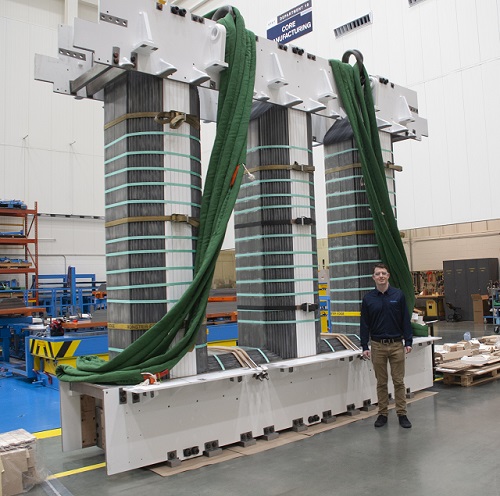
Core and Coil
For an electrical designer, the core and coil is the fun part! Like most engineering practices, designing the core and coil is a lovely game of tradeoffs for optimization. In particular, this is the part where the designer calculates the volts per turn. From the transformer equation V/T = 4.44BAf, the designer can vary the volts per turn by adding or subtracting turns from the high voltage and low voltage accordingly while maintaining the correct ratio for voltage transformation. What designers are controlling is the B – flux density (think no-load loss) and then adjusting the A – area of the core accordingly. This practice allows the design to hone in on an optimized amount of copper and core steel, thereby offering you a transformer at an optimal cost.
Of course, that is not the only thing electrical designers do. They also manage the kind of winding that is optimum in a given space, the turns per disc, strands per turn, tap changers, tapped windings, the strength of the windings for a short circuit fault, the dielectric clearances, the load and no-load losses, the impedance and much more. Many variables exist, and these variables should be considered levers of optimization for the designer.
Freedom for an electrical designer to make choices is what brings you an optimized transformer cost, and that is why manufacturers often encourage specification writers to consider carefully the limiting parameters he/she might include in a specification. While limiting parameters is unavoidable in some cases, such as when a transformer might need to fit through a tight place or, as a retrofit, need to be physically sized a certain way, in other cases, “designer’s choice” may be the best option. Specifying CTC only, a minimum radial dimension of a copper strand, exactly how taps must be arranged or a minimum key spacer thickness can lead to higher cost and, often, no real benefit. These are items that take away elements of a designer’s ability to give you an optimized design at an optimized price.
While you may have good reasons for including a variety of limiting parameters in your specification, understanding how these design parameters can impact cost is important as you evaluate whether or not they are critical to the application. As these levers of optimization are taken away from the electrical designer, designers have to make changes accordingly. These changes can end up resulting in a design that is not as optimized cost-wise as it could have been. Regardless, if what you are asking is possible, then it can be done. Make sure to clearly state your intentions so the designer understands what you are looking to receive. Depending on complexity, an open line of communication with your manufacturer may be necessary as the company starts the design process.
External Design (Tank, Accessories and Controls)
The tank design begins with any site dimensional limitations, shipping restrictions and oil preservation system requirements. These factors influence the cooling layout, drive equipment placement and overall unit footprint. Including site drawings and photos ensures no details are overlooked, especially if the design is a retrofit.
Any spare parts or future equipment provisions should also be included so they can be factored into the proposal and, subsequently, the order.
Accessories play a key role in how the user interacts with the transformer, and the possibilities for selection and placement are limitless!
Explicit, precise instructions on not only what accessories are necessary, but any preferences on vendor, configuration and segment placement, are important to include in your specification.
If no preferences are indicated, the manufacturer will select and place equipment per IEEE and its own internal standards.
While this equipment will undoubtedly be effective, it might not fit your preferences exactly. Examples of accessories include bushings, arresters, valves, gages, sensors and cooling fans.
Any spare parts or future equipment provisions should also be included so they can be factored into the proposal and, subsequently, the order.
With the introduction of new devices and monitoring systems, control cabinets are more complex than ever. To make sure the controls design goes smoothly, include model-specific information for all preferred devices within the control box so proper wiring diagrams can be acquired. Possible devices could include electronic temperature monitors, LTC controllers, relays and terminal blocks. If any devices have preferred mounting locations within the control cabinet or wiring requirements, such as terminal style, those should also be noted.
Site environmental conditions should always be provided in detail as they drive external clearances, accessory rating selection, control box enclosure design and equipment mounting. Examples include extreme altitudes, temperatures, pollution exposure, sound limitations or levels of seismic activity. Unless you are designing a substation for the first Mars settlement, odds are the manufacturer has seen your conditions before and can arrive at a solution that best fits your needs.
When considering external transformer design, writing an effective specification can be simple: Focus on your needs. The manufacturer cannot tell you exactly what you need, as a multitude of factors drive those decisions. What the manufacturer needs is clear language describing all vital, non-negotiable requirements. Provide as much information as possible up front, free of contradictions. Disconnects between the specification and customer requirements can often lead to questions, miscommunication and additional costs for late changes in the design. If areas exist where you have no preferences, trust the manufacturer’s expertise to fill in the gaps between your needs to arrive at an optimized external transformer design.
Testing and Commissioning
Testing and commissioning are the final pieces to bringing that new transformer to its pad in your substation. Testing includes the final quality checks before the transformer gets wired up and fired up after commissioning. Once again, the IEEE makes testing easy in C57.12.00 and C57.12.90 [1], [2]. Reference C57.12.00, Table 17, to see all standard tests for Class 1 and Class 2 transformers. Then reference C57.12.90 to get more information on each test. You can use the IEEE standard list of tests in your specification and then make adjustments according to your particular needs.
You might be looking for your transformer manufacturer to handle freight, rigging and installation as well, which means shipping the transformer to you, placing the transformer on your pad and installing it according to the manufacturer’s — and your — requirements. Installation typically involves a set of field tests to verify the condition of the transformer post-shipping then placing the transformer on your pad. For these items, supplying as much information about the substation as possible is important to ensure a successful installation. Details could include an ideal route to the substation and layout drawings of the actual substation and/or pad on which the transformer will sit. The more information you provide, the more accurate a quote you will receive. Complete information will also allow for a more comprehensive plan to get your transformer hooked up as fast as possible with no delays.
From core and coil to external design, the common thread is effective communication. Be clear and concise about your requirements and remember that good specifications are crafted over years with multiple inputs and revisions, all in the pursuit of acquiring the perfect transformer.
Conclusion
An exorbitant amount of factors need to be considered — and documented — when writing a full transformer specification. While the aforementioned tips and tricks may be useful, they merely scratch the surface of what it takes to finalize a full specification. From core and coil to external design, the common thread is effective communication. Be clear and concise about your requirements and remember that good specifications are crafted over years with multiple inputs and revisions, all in the pursuit of acquiring the perfect transformer.
As a final example as to why transformer specifications are so important, note that it is not uncommon for transformers in rural areas to require additional external clearances on the cover for local wildlife. If you are one of those utilities needing to adjust for this, make sure you tell the transformer manufacturer whether you expect the critter landing on the cover to be a squirrel or a stork!
References
- IEEE C57.12.00-2015 – IEEE Standard for General Requirements for Liquid-Immersed Distribution, Power, and Regulating Transformers
- IEEE PC57.12.90 - IEEE Draft Standard Test Code for Liquid-Immersed Distribution, Power, and Regulating Transformers

Charlie Bowman
Charlie Bowman is a Lead Mechanical Engineer at SPX Transformer Solutions where he manages the external design team. He received his Bachelor of Science in Mechanical Engineering from Purdue University in 2018. His first position out of school was with SPX Transformer Solutions in the Engineering Development Program, which led him to the current role he has held for just under a year. He enjoys golf and hiking with his wife in Pewaukee, Wisconsin.