
BUSHING FAILURES: A DIFFERENT APPROACH
Foreword from the Editor in Chief
I recently asked Thomas Linn to join our Technical Advisory Board (TAB) for the TT Community and also the Editorial Board of the TT Magazine. As you read this article you will understand why. Thomas has a tremendous grasp of all things technical relating to transformers, and beyond to substations, transmission and likely, we will find out, about the entire grid. Thomas is also a wonderful gentleman and someone I have gotten to know through our work together on the Comet Conference. In the world of EPRA, we consider him to be a Fellow, someone who has risen to the top in his profession by being willing to give of himself and his expertise freely and fully to make our professional better. Get ready to explore a different approach to Bushing Failures from a true expert in our field.
Transformer bushings are one of the most critical components of a transformer. Today, up to 20 % of major failures on high voltage transformers can be tracked back to bushings [1]. Almost half of these failures result in catastrophic failures like explosions, fires or oil spills. The cost of these damages and the lost opportunity to deliver energy could be several hundred times higher than the price of a bushing. Even a failing bushing which will not lead to a catastrophic failure can harm people due to exploding porcelain insulators and broken fragments that can be catapulted through the air by the force of the breakdown arc. The safety implications of this are tremendous. This article as a first of the series of two will discuss different failure mechanisms and causes for failures.
Introduction
Today, most power transformers will have two sets of bushings during their lifetime because transformers are expected to last 50 years, while bushings have an expected lifetime of 25 years. Experience suggests there are two points of failure within the lifetime of the bushings.
-
When a bushing reaches an age of 10 to 13 years, failure is possible due to the design, transformer operation and potential quality issues, even though they are not “aged out” in life-cycle management terms.
-
When bushings reach 20 to 30 years of age, which is considered the normal lifetime, they are more prone to failure merely because of age. While bushings can fail before reaching the age of 10, it is also true that there are bushings installed in transformers that are more than 50 years old, so age alone cannot be the determining factor.
To avoid costly replacements of bushings based on age alone, and not due to their real condition; while detecting upcoming faults, it is essential to know the failure mechanism and failure causes for bushings. Bushing conditions are often influenced by different operating conditions of the transformer. These operating conditions can be overheating, load variations, frequent exposure to transients and intensive pollutions. Designs, types and manufacturing processes can have a significant impact on the lifetime of bushings as well.
Failure Mechanisms
Impact of Operating Conditions
The operational environment has quite a big influence on the stress on electrical assets, and some assets react uniquely to different stresses. Over the years, transformers have improved in design, especially for handling transient voltage stress. Further, local overheating especially due to bad contacts or overloading can be another factor for degrading the bushing health. Changes of load conditions, especially for the air insulated side of bushings which are connected to overhead lines, will results in changing mechanical forces, pulling on the bushing heads. Through-faults provide an additional transient mechanical stress.
Impact of Electrical Transients
Electrical transients are short bursts of energy introduced into the network which results in short term over-voltages with the duration of several nanoseconds (ns) up to hundreds of microseconds (ms). Depending on the duration and length of transients there can be Very Fast Transients (VFT – rise times in ns-range), Lightning Transients (low ms-range) and Switching Transients (hundreds of ms-range).
Amplitudes of transients are measured in a factor per unit (p.u.). This factor measures how many times higher the transient voltage peak is than the peak voltage of the line voltage. In a 220 kV network, the phase-to-ground peak voltage would be 179.6 kV. A transient with a voltage peak of 1.5 p.u. would be 269.5 kV peak. Obviously then, the duration of an overvoltage is relevant for the risk of a bushing.
Bushings are designed based on the Basic Insulation Level (BIL- representing the lightning impulse level), according to IEC 60137 or IEEE C57.19.01. The lightning transient stress as well as the switching transient stress for bushings seem to be well covered by that standard. Further, the maximum amplitude of transients can be effectively controlled by using surge arrestors.
Very Fast Transient (VFT) Stress
VFTs are relevant for SF6/oil bushings where a Gas Insulated Switchgear (GIS) is directly connected to a transformer. The SF6/oil bushing in this case is providing the interface between the GIS installation and the transformer. VFTs can happen due to an operating circuit breaker, but more likely due to an operating disconnect switch. Depending on various parameters (which will not be discussed in this article) the peak amplitude can be up to 2.5 p.u. or higher. These transients provide a high voltage and high frequency stress to the bushings. The condenser cores of bushings in most of the cases are not specifically designed and tested for that type of high voltage combined with high frequency stress.
Bushing condenser core cross section - design example
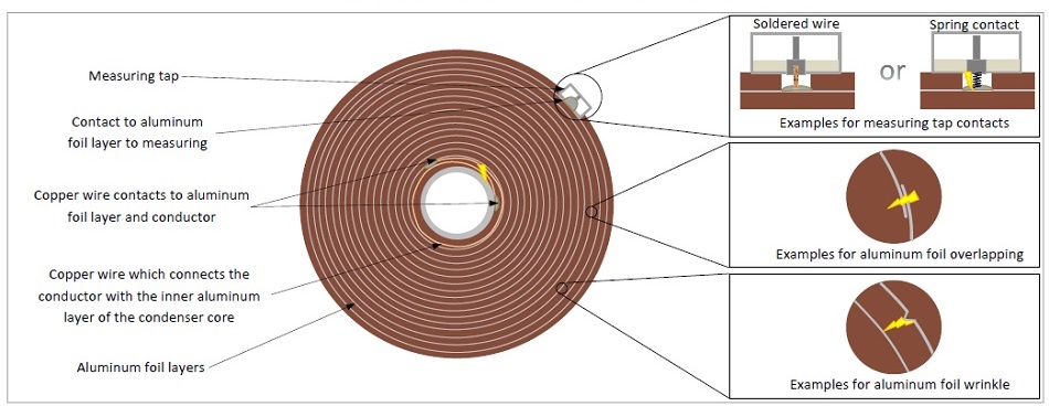
Figure 1. Contact designs and foil overlapping in a bushing condenser core
For these high frequencies, the inductances of the conducting materials used to produce the bushing condenser cannot be neglected, since the electrical field distribution is different than the one for normal operation frequency application.
Figure 1 shows some critical points for transients. In some designs the connection of the conductor or conducting tube is contacted to the inner foil with a copper wire, which is winded together with the paper. This provides a relatively high impedance for VFTs and creates a high voltage drop which can create sparking in the area of this wire. Over frequent occurrences the insulation material and even the connecting wire can slowly be destroyed. This will lead to a permanent or periodic sparking due to normal operation. It can further erode the insulating material and can lead to partial breakdowns, followed by a potential complete breakdown.
The measuring tap design is also relevant for transient stress and sparking. Figure 1 presents two different designs of measuring taps. The first one has a copper wire soldered to the contact system of the last aluminum foil and the inner pin of the measuring tap. The second design is using a spring as contact, which makes the assembly easier, but it is more prone to transient stress since the spring provides a comparably high impedance. Each transient event can generate a sparking in the bushing tap and can lead over time to bushing failure.
A third sensitive point for transients is the overlapping of the foils. The insulation layer between the two foil ends is only one thin layer, either impregnated with oil or resin. During a transient event, these two foil ends can have different potentials where the potential difference is high enough to create a sparking between the overlapping foil ends. Over a longer time period, this can lead to material erosions and finally the failing of the bushing.
Wrinkles or kinks in the foil or at the foil edges can also be introduced during the manufacturing process. If very serious, they usually get detected during the HV routine test as part of the manufacturing process. Nevertheless, non-detected wrinkles or kinks under normal operating stresses are not a concern. Only under frequent transient stress can they develop the same behavior as described. Ultimately the high electrical field caused by the sharp edges under a fast rise-time impulse stress is the dominant factor for causing a partial or complete breakdown.

Switching and lightning transients
Switching transients are important for transformer bushings, where transformers are installed close to high voltage breakers or disconnect switches, which are frequently being operated. This applies to transformers close to capacitor banks or reactors, where switching will take place almost every day. Depending on the distance and how the transformers are connected to the breakers/disconnect switches, the impact can be significant. A long overhead line connection will provide high impedance, which will attenuate the wave and minimize the impact. A cable connection with its high capacitance will attenuate the switching wave as well. The parts involved and the failure mechanisms and developments are similar to the VFTs, but the severity is lower due to a slower rise time.
High temperature
High temperatures due to overloading or overheating of bad contacts can cause the bushing insulation material to degrade. For resin impregnated paper bushings (RIP) or resin impregnate fiber bushings (RIS), the “glass transition temperature” determines the maximum permittable hotspot temperature. The glass transition temperature is a material property which can be influenced by the resin system composition and is usually above 130°C and below 140°C.
High glass transition temperatures lead to higher brittleness and the material tends to create micro-cracks, which can lead to partial discharge (PD). Conversely, too low glass transition temperatures limit the maximum allowed hotspot temperature. The glass transition temperature must always be higher than the maximum allowed hot spot temperature given by IEC 60137 and IEEE C57.19.01.
For oil impregnated paper bushings (OIP), the decomposition of the paper insulation and the insulation oil are important considerations. Figure 2 presents the relationship between accelerated aging expressed by the aging factor for different temperatures. The paper that is usually used in bushings is normal kraft paper (IEEE or IEC). At about 95°C the aging acceleration factor will be about 1. The increase of the operating temperature by 5K will increase this factor to 2, which means doubling the aging speed. The diagram in Figure 2 has been established for insulation paper in transformers, but is valid for the insulation paper in OIP bushings as well.
Mechanical stress
For transformer oil/air bushings, only the permanent and transient mechanical stress introduced by overhead lines will now be considered.
As shown in Figure 3, mechanical forces are being introduced by a connected overhead line for the air part of the bushing as vertical and horizontal forces.
Static forces are determined by the weight of the overhead line and the designed tension to guaranty the minimum safety clearance of the overhead line to the terrain at maximum sag.
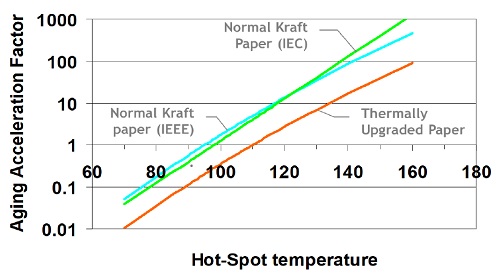 Figure 2. Aging acceleration due to temperature for different papers [2]
Additional loads, typically snow, can contribute to the static loads along with seasonal and temperature related, slowly changing variations. Additionally, the changing load current of an overhead line will result in different temperatures of the wire conductor itself and result in a different quasi-static mechanical force. Transient mechanical forces can also be introduced by wind and through-faults.
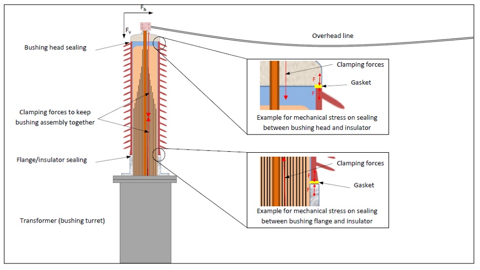 Figure 3. Mechanical stress: examples for stress on the bushing sealings
Bushings are designed to withstand static and transient mechanical forces. Nevertheless, excessive mechanical forces can mechanically destroy a bushing. The quasi-static forces and the transient force do have the potential to weaken the sealing system of bushings. The details in Figure 3 show the compressing of the gaskets on the pulling side. It could pull open between the sealing and flange/porcelain/head (depending on the design) as a possible defect. This would lead to moisture ingress. The moisture would in this case presumably stay between the bushing core and the inner porcelain or inner composite insulator surface. The moisture will, over time, migrate into the condenser core as well, but before that, it can also result in a breakdown along the inner insulator surfaces.
It needs also to be mentioned here that there are differences in design of the sealing systems, not only between different manufactures, but also between different types of bushings from the same manufactures.
Moisture
Moisture in bushings can be caused by several situations. Leaking gaskets due to mechanical stresses, or aging as explained above, will be the most common cause for allowing moisture to ingress into the bushings. Moisture can be found in the insulation paper and/or in the insulation oil.
When it comes to moisture, OIP bushings behave similarly to transformers, with the difference being that within the condenser core the oil cannot circulate that freely. This means that if the moisture slowly creeps into the bushing, it will initially remain outside of the condenser core and within the outer layers of the core. Over time the moisture will ingress further into the bushing. It is also important to understand that the aluminum layers are also slowing down the crosswise distribution of the moisture. The moisture will mainly impregnate lengthwise into the bushing core.
Since moisture cannot impregnate pure resin, the moisture in a RIP bushing will be found in the paper. Comparing the RIP bushing cores to OIP bushing cores, the resin will provide an additional barrier against the crosswise moisture impregnation. As for the OIP bushings, the lengthwise moisture impregnation will be the major way for moisture to migrate into the bushing. Besides leakages, RIP bushings can also get “wet” due to improper storage. To address this issue, a plastic bag covering the transformer side of the bushing, wrapped air-tight with tape and a silica gel package inside will work) to keep the bushing moisture free for shorter term storage (just a few months. For longer storage periods the transformer side of the bushing needs to have a storage tank filled with transformer oil.
RIS bushings do not have any paper involved. The winding material is a synthetic mesh, and the resin is a filled epoxy system. Due to that, no moisture can migrate into the RIS bushing core.
Process/ Design
Today the design, production and manufacturing systems for bushings are very well controlled through quality control processes and they must be tightly controlled and monitored. Common throughout all bushing types are: the contacts between the inner foil layer and the conductor/conducting tube; and the contact between the outer foil layer and the measuring tap (see also Figure 1). There are different techniques to making this connection, like conductive gluing, soldering, spring contacts or combinations of these. It may be necessary to drill into the RIP body or cut into the insulating paper to access the contacts system of the respective foil layer. It is extremely important not to drill or cut through the aluminum layer as that would make the bushing unusable.
During the winding process any wrinkles and kinks need to be avoided, as mentioned previously. The homogeneity of the foil layer distances is very important to achieve an equalized field distribution across the whole bushing condenser core. Further, cleanliness is an important factor as well. Avoiding foreign particles (especially conductive particles) that can fall on the paper or the aluminum foil during the winding process and being wound into the bushing condenser core will create potential failure points when in operation.
The casting process for RIP bushings must be controlled in a way that delamination cannot take place and that there are no voids that can build up. Voids are sometimes difficult to be detected during routine testing due to the known ignition delay for PD in voids in solid insulations. If not detected, they can cause severe problems for bushings in service.
Conclusions
The knowledge about operating conditions, different designs, technologies and stresses for bushings will allow operators to gain more confidence in their assessments of the actual bushing condition. Not only electrical stresses but also mechanical and thermal stresses on the bushings need to be known.
In a future article, we will describe how this knowledge can be combined with different detection methods and approaches to detect incipient faults and minimize bushing failures.
References
1. A2.37, CIGRE WG, Transformer Reliability Survey: Interim Report, s.l.: No. 261, ELECTRA, 2012
2. Bérubé, Jean-Noël, Aubin, Jacques and McDermid, William M, “Transformer Winding Hot Spot Temperature