
CRITICAL COMPONENT MONITORING
Transformers equipped with OLTCs are crucial components in the power system due to their purpose of maintaining the voltage output desired. To maintain these voltages, they are required to perform frequent operations. However, when maintained properly and operated within design limits, these components should provide many years of reliable service.
This article will document some of these failure modes and steps that can be taken to detect the symptoms of failure before an undesired outcome occurs.
Transformers equipped with on-load tap changers (OLTCs) are crucial components in the power system due to their purpose of maintaining the voltage output desired. To maintain these voltages, they are required to perform frequent operations. However, when maintained properly and operated within design limits, these components should provide many years of reliable service.
Modern technology, such as vacuum interrupters in the diverter switch, has greatly improved OLTC performance.
However, there are still many OLTCs in service today based on older technology which is much more susceptible to significant wear and tear on critical elements. This wear is frequently the cause of misoperation or even unexpected failures when not properly maintained.
This article will document some of these failure modes and steps that can be taken to detect the symptoms of failure before an undesired outcome occurs.
The suggested overall maintenance strategy is illustrated in Figure 1 [1].
There are several methods used to determine whether the equipment is operating normally. They include time-based maintenance (TBCM), condition-based maintenance (CBM), online condition maintenance, and traditional time-based maintenance (TBM or number of operations). These various methods can be employed individually, but in most cases, they are combined for a more thorough analysis of operating condition.
Transformers equipped with on-load tap changers (OLTCs) are crucial components in the power system due to their purpose of maintaining the voltage output desired.
The type of OLTC should influence the plan for inspections and online/out-of-service testing.
There are two distinct types of OLTCs: bolt-on or welded-on OLTCs – designed to fit onto the sidewall of a transformer (Figure 2); and in-tank type OLTCs – designed to install inside the tank and suspend from the cover (Figure 3).
Both designs can include arcing in oil type diverter switches using resistors, series reactors or vacuum interrupters. These various components are designed to carry the circulating currents during a tap change.
Failure Modes and Diagnostic Methods of Detection
The failure modes of both designs can be the same or segregated, depending on the type of testing or monitoring performed.
Some methods are more effective than others. While some failure modes can be detected with sensors and systems, as noted below, others can only be determined with a combination of sensors and laboratory testing (oil, for example).
The chart in Figure 4 [1] provides guidance on the most effective technique at detecting these common failure modes.
Some examples of online monitoring techniques include a commonly used monitoring method know as temperature differential, which is most commonly used for externally installed OLTCs. While less common, in tank diverter switches can also be monitored in a similar fashion.
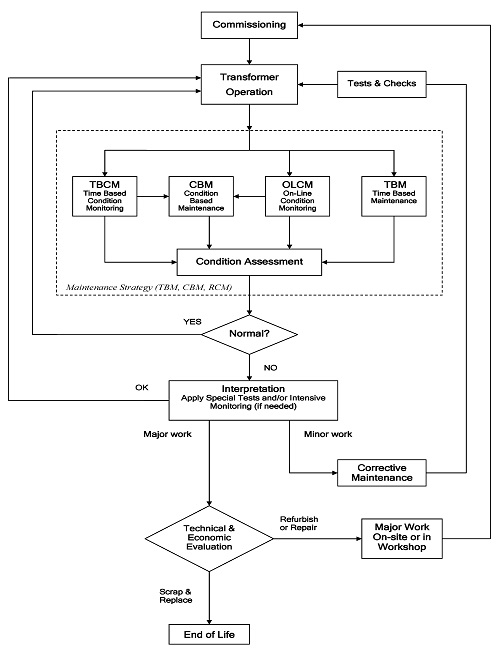
Figure 1. Transformer maintenance strategy [1]
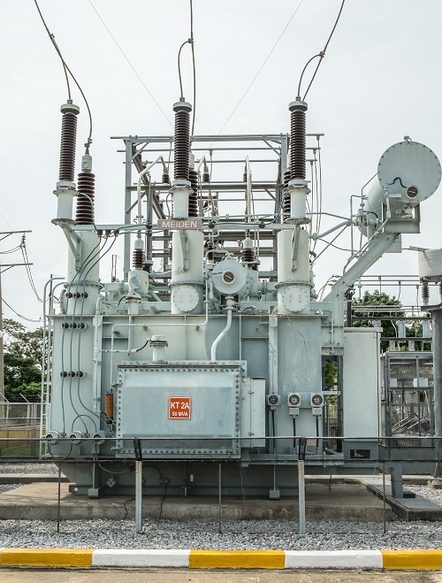
Figure 2. External type OLTC
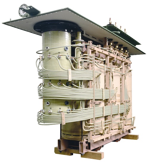
Figure 3. In-tank type [2]
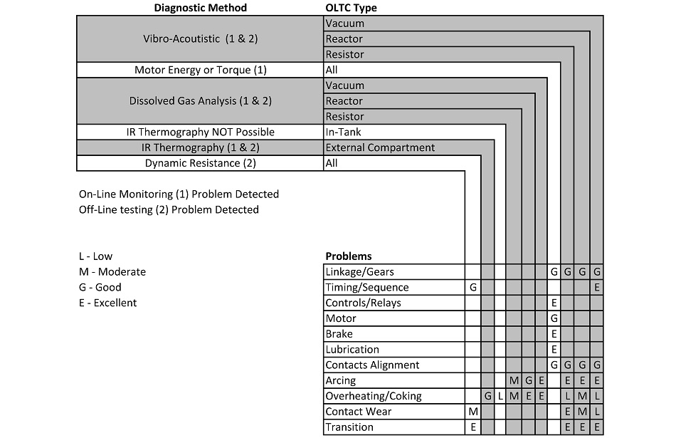
Figure 4. Diagnostic methods for OLTC problems (taken from [1])
The technique employs the measurement of the oil temperature within the OLTC compartment and the oil temperature in the main tank. As there is little to no heat source inside a normally operating OLTC compartment, the oil temperature of the main tank, due to the heat generated by the core and coil assembly, should always be higher when compared to that of the OLTC compartment. The theory follows that the OLTC oil temperature is ALWAYS lower than the oil temperature of the main tank.
However, when contacts in the OLTC compartment begin to have an issue, they will overheat and contribute to the oil temperature that will exceed that of the transformer. Therefore, the rolling average difference between the two is normally below "zero". Once it reaches an alarm point (suggested at +10°C differential), the unit requires immediate attention. Figure 5 details an event where the differential (yellow trend) exceeds the zero crossing, and alarms about three days after that event.
There are still many OLTCs in service today based on older technology which is much more susceptible to significant wear and tear on critical elements. This wear is frequently the cause of misoperation or even unexpected failures when not properly maintained.
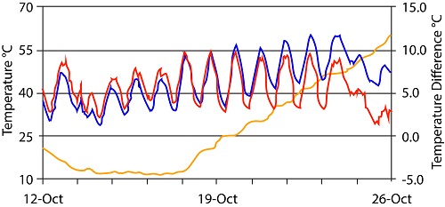
Figure 5. Details of OLTC oil (blue trace) and main tank oil (red trace) temperatures, together with a rolling average differential (yellow trace)
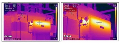
Figure 6. Confirmation of a serious issue inside the OLTC compartment using IR Thermography
As with any alarm, there needs to be some other correlating evidence to provide further confidence in the alarm. One such method, in this case, is IR Thermography. When scanning the equipment, it will become evident to the inspectors that the condition alarmed above is occurring. Figure 6 provides such example.
A further method used to provide evidence to confirm a fault is DGA testing and Duval Triangles developed for certain types of OLTCs (Figure 7).
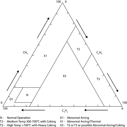
Figure 7. Duval Triangle [1,3]
IEEE C57.139-2015 – IEEE Guide for Dissolved Gas Analysis in Transformer Load Tap Changers, provides guidance on DGA for OLTCs and should be required reading for those involved in this work.
This method uses the concept of comparing “hot metal” gases with “arcing gases”. The area denoted as “N” equates to “consistent values” independent of the number of operations. It is crucial to note that each make and type of OLTC will have a different gassing signature. Therefore, one rule cannot be applied broadly.
Monitoring in-tank diverter switches using temperature differential would require RTDs to be installed in the diverter switch cover or fiber optic temperature sensors installed in the diverter switch oil tanks. When monitoring single phase diverter switches, the three diverter switches should be compared to each other as well as to the main tank. If any of the diverter switches varies by more than the programmed threshold, an alarm is set to alert the user that additional investigation should be performed to identify the problem.
Mechanical Defects and Observable Symptoms for Problems
The OLTC is the major mechanical moving device on a transformer. As with any mechanical device, movement equates to wear of components over time and frequency of operation.
There is a mechanical operations counter on every OLTC. It records an event (adding) every time the OLTC operates. It does not record which position it moved from and whether it moved up or down. The tap position indicator on every OLTC is a mechanical device that provides the current tap position and the ‘range of movement’ the mechanism has operated, which is recorded using resettable drag hands on the indicator.
By the relatively simple addition of a remote tap position sensor, a monitor will track and trend the total operations, number of operations at each position, and the I2T to provide an idea of contact wear. If the monitoring system is also providing control, the tap position sensor may also be used to provide positive feedback to the control system that the tap changer successfully changed taps when the raise or lower command was issued.
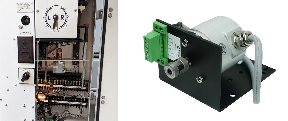
Figure 8. Retrofit of remote OLTC tap position sensor onto existing OLTC motor shaft
It will also monitor and alarm on the frequency of reversing switch operations; the time since it last moved through that position to "wipe the contacts".
When this reversing contact remains in a static state for extended periods, it can lead to overheating due to a high resistance film forming on the contact surface.
This overheating, if not addressed, will result in an excess buildup of carbon on the reversing contact and eventual "coking", as illustrated in Figure 10, causing the tap changer to become inoperable.
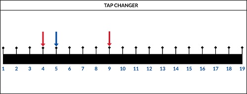
Figure 9. WEB view of OLTC range of motion (red arrows) and current position (blue arrow)
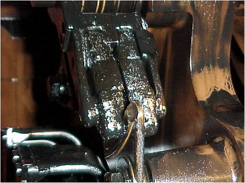
Figure 10. Coking due to excessive heating of a stationary contact
The motor current method is a common way to understand if there are lubrication problems with the mechanism, as shown in Figure 11.
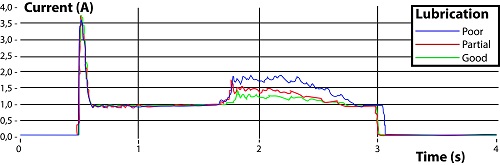
Figure 11. OLTC drive lubrication problem detected by motor current measurement
A more refined method is to monitor the total motor energy for any deviation in the joules required to either load the springs of the OLTC or to operate the actual direct drive type of mechanism.
Measuring both the voltage at the motor terminals and the current drawn for each motor operation records the trace and computes the joules. Any variation in the amount of energy drawn (higher or lower) is an early indication of problems. Figure 12 provides a view of the data.
Vibro-Acoustic Diagnostic Principle
Every operation of any on-load tap changer produces a characteristic acoustic wave pattern that transmits through the oil and structural elements (beams, plates).
It has been shown on numerous occasions, in the lab and in the field, that any degradation in the internal condition of the OLTC will produce detectable changes in the acoustic signature. Inversely, a stable OLTC will show consistent signatures [4].
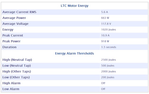
Figure 12. Details of total motor energy consumed during a tap change
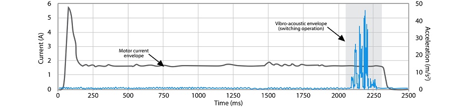
Figure 13. Typical OLTC acoustic signature [5]
Figure 13 shows typical measurements of motor load current and OLTC vibrations. These measurements make it possible to check various parameters such as operating times, current amplitude, current profile (particularly the inrush current), delays between motor start and switching, and switching time. Detailed analysis of switching vibrations also makes it possible to identify the amplitude and duration of events caused by separating- and closing-switch contacts [4].
Many legacy OLTCs remain in service, and most require frequent inspections/testing, often involving outages which can be difficult to arrange.
Online monitoring of the unique failure modes, which vary as a function of the design of OLTC, has proven to reduce unexpected failures and allowed the transformer owners to move from a time and/or number of operations-based maintenance to a condition-based maintenance program. This identifies the possible defect and allows for planning of the outage with the proper crew, equipment, and spare parts to bring the OLTC back into correct functional operation.
References
-
Cigre Technical Brochure TB 445, Guide for Transformer Maintenance February 2011
-
Photograph courtesy of Maschinenfabrik Reinhausen, Germany
-
ABB Technical Bulletin 1ZSC000498-AAA en, “Dissolved gas analysis in on-load tap-changer oil”
-
Marc Foata et al., “Field experience with the implementation of a new on-line vibro-acoustic diagnostic for on-load tap changers,” Doble Paper 2005
-
Picher et al., “A New technology for monitoring transformer tap-changers and bushings and their integration into a modern IT infrastructure,” Paper A2-101, Cigre Conference 2012, Paris France