Credit: IMCORP
RENEWABLES AND BATTERY STORAGE
Yes! We can’t control the energy source of wind and solar and connected battery storage systems, but we can ensure plant reliability by implementing best practices to maximize uptime when generation is available. Unlike oil and gas-powered generation facilities, power cables and transformers at utility scale renewable sites play a much bigger role connecting the distributed generation to the grid. Unplanned collector system outages can easily cost over one hundred thousand dollars per event including the impacts of repair cost, revenue loss and power purchase agreement penalties. In fact, simply based on typical cable system failures of cable systems not properly commissioned, the average utility scale site will experience more than 15 failures yielding over $1.5 million in losses over a 25-year plant life.
Unlike oil and gas-powered generation facilities, power cables and transformers at utility scale renewable sites play a much bigger role connecting the distributed generation to the grid.
When wind and solar energy are available, we need to ensure the medium voltage (MV) collector systems are reliable so revenues, operation and maintenance (O&M) budgets, and power purchase agreements are not negatively impacted. Scarcity in material supply chains and experienced resources are introducing additional risks. For example, the frequency of cable manufacturing defects, while only 5% of total defects found, have doubled from what the industry experienced over a decade ago. Many veterans from the more mature utility-scale wind industry are making efforts to apply lessons learned to solar and battery applications.
In fact, simply based on typical cable system failures of cable systems not properly commissioned, the average utility scale site will experience more than 15 failures yielding over $1.5 million in losses over a 25-year plant life.
New industry recommended practices and guidance are available, but the knowledge is not evenly distributed. In addition to identifying how cable and transformers fail, this article provides insight into industry trends and specific case studies illustrating the benefit of implementing the latest in recommended proactive quality control (QC) commissioning, and maintenance practices.
Renewable Industry Learning Curve
According to American Clean Power (ACP), utility scale wind development ramped up in North America in the mid 2000s. The industry spent years developing solutions to many unforeseen reliability challenges including challenges with the collector systems. According to ACP, utility scale solar didn’t reach the scale of wind until 2013. Data collected from about 65% of wind and solar collector systems built between 2014 and 2019 and commissioned using line scanning technology comparable to cable and accessory manufacturer factory QC tests (Table 1) shows a remarkable learning curve story. Wind systems meeting the cable and accessory manufacturers’ standards maintained a consistent high level of performance whereas solar systems took 5 years to catch up. This strong correlation is also supported by onsite experience. We conclude that it took about 5 years for many solar developers to adopt training, construction, and commissioning best practices. In the last couple years, utility scale energy storage projects have ramped up, much like solar did in 2013, which brings us to the point. Our industry has a great opportunity to shortcut the learning curve with yet another round of new developers and contractors by implementing best practices including the ones in this article.
Our industry has a great opportunity to shortcut the learning curve with yet another round of new developers and contractors by implementing best practices including the ones in this article.
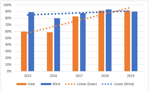
Figure 1: First pass performance of wind and solar MV cable systems portraying % of systems meeting manufacturers’ standards as shown in Table 1
Implementing Best Practices to Prevent Transformer Failures
The fleet of transformers at utility-scale renewable sites plays a decisive role in connecting the distributed generation to the grid. Going beyond routine maintenance activities with best practices and reliability strategies for transformers is crucial to ensure the efficient and uninterrupted conversion and transmission of generation from wind and solar sources. Although transformers are designed to last for decades, a number of drivers can push them to premature failures, such as extreme heating, mechanical stress, contamination, extreme voltage stress, and corrosion of external components.
The insulating paper is the life of the transformer. The transformer paper is immersed in a dielectric liquid, which enhances the strength of the paper and serves as an inhibitor to heat, oxidation, and moisture, all of which contribute to a decline in performance and can lead to failure. If the paper is compromised, PD occurs and creates a destructive feedback loop that can eventually lead to failure. Additionally, a transformer leaking from its main valve or bushings can expose the paper, causing it to rapidly dry and initiate PD.
While there are extreme cases when a failure occurs without warning, proper commissioning, proactive maintenance, and regular monitoring of your transformers are key to fleet reliability, longevity, and avoiding premature failure. Implementing best practices and reliability strategies helps utility-scale renewable sites navigate the challenges of maintaining a robust transformer fleet in an ever-evolving energy landscape.
Commissioning Tests for Transformers
Main power, pad mount, and grounding transformers are typically tested over multiple stages during the commissioning process. Before a transformer leaves the factory, the buyer should ensure it has been properly tested. Ideally, key tests are repeated in the field after installation and during the initial energization process to ensure against transportation and installation damage. IEEE guides, ACP RP 601, and NETA ATS 2021 all recommend a battery of tests, including electrical, chemical, and infrared thermography. Electrical tests should include a turns ratio test, a winding resistance test, and an insulation resistance test. For the main power transformer, a sweep frequency response analysis is recommended. Chemical tests should comprise measurements such as the list in SDMyers’ “CriticalPac,” which includes interfacial tension, dielectric breakdown voltage, neutralization number, relative density, color, visual, Karl Fischer moisture, dissolved gas analysis, liquid power factor, oxidation inhibitor content, dissolved metals, and furanic compounds. After energization and the system is under load, infrared thermography of the transformer components, such as external bushings, connections, cooling fins, and the surfaces, is recommended as part of an ongoing electrical maintenance plan (EMP) that adheres to NFPA 70B standards.
Transformer Case Study
A site in the United States experienced a failure of their main power transformer. The owner was running a costly backup generator while awaiting delivery of a main power transformer. In the purchase agreement, the owner agreed to manufacturer warranty terms which outlined required acceptance testing, including a baseline electrical power factor test as well as weekly dissolved gas analysis for a period of three weeks following energization. Due to a limited budget and the steep and unexpected expense of rewiring a portion of the site for compatibility with the new transformer, management declined to provide the funds necessary to complete the commissioning tests on the new transformer. After nearly a year, the owner decided to conduct chemical testing to get a baseline on the health of the transformer and indicated that a power factor test could also be conducted during an upcoming planned outage. The chemical test indicated active arcing. To provide a comparative analysis, a chemical test was conducted 48 hours later, revealing concentrations of some key indicators had doubled. The owner was advised to immediately take the transformer offline but instead continued utilization. Within four days, the transformer exploded, caused damage to surrounding assets, and was a total loss. With no true baseline data or ability to perform a root cause analysis, the ultimate cause of the transformer failure remains undetermined. Additionally, the manufacturer was unable to honor the warranty because the acceptance testing outlined in the purchase agreement was never performed. Failure to properly commission and monitor the health of the new transformer turned into more than a million-dollar mistake.
Implementing Best Practices to Prevent Cable System Failures
The primary cause of modern cable system failure is human induced damage exacerbated by extreme voltage conditions. Modern, medium and high voltage cable systems fail due to a voltage driven erosion process associated with a ‘micro arcing’ phenomenon called partial discharge (PD). PD can arise from an extreme focus of electric stress and a lack of the appropriate solid insulation. 93% of PD activity is not active at operating voltage but can be triggered by voltage transients which are common at renewable sites. Transients should be limited by surge arresters but unless properly tested and repaired, industry data shows about 40% of newly installed cable systems will have at least one substandard PD site active below protection levels, so effective commissioning to remove these risks is critical.
Commissioning Tests for Cable Systems
In their 2023, “Wind and Solar Underground AC Collection System Cable Testing," ACP recommends using offline 50/60 Hz partial discharge testing with 5pC sensitivity as a diagnostic method for both commissioning and aged cables. The IEEE 1185 “Recommended Practice for Cable Installation in Generation Stations and Industrial Facilities” states “PD testing is recommended for post-installation testing of medium voltage power cable systems. Experience has shown this test to be the most effective means of the detection and identification of issues associated with cable system accessories (improper cable preparation, interface contamination, improper alignment of stress control layers, improper shrinking, etc.)” and “when testing a complete cable system, each component should meet the partial discharge requirements” and provides the standards in Table 1 as a reference.
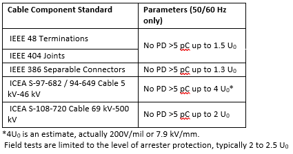
Table I: Manufacturing Standards PD Test Specification
Cable System Case Study
In this case study involving over a dozen renewable energy projects with identical construction specifications and executed by the same pool of contractors, the efficacy of two distinct test approaches—IMCORP's AI-based line scanning technology and a conventional VLF (Very Low Frequency) commissioning test—was evaluated. The study encompassed a significant cumulative length of 1,616 miles over a four-year observation period. The circuits subjected to IMCORP's advanced technology demonstrated an outstanding performance, revealing an impressively low failure rate of 0.03 failures per 100 miles per year. In stark contrast, a subset of cables spanning 105 miles, undergoing VLF commissioning tests, exhibited a substantially higher failure rate of 2.53 failures per 100 miles per year over a three-year observation period. Notably, the IMCORP-tested circuits demonstrated an 81-fold improvement in performance compared to their VLF-tested counterparts. The study also unveiled a disconcerting parallel between the failure rates of VLF-tested circuits and new cable systems not subjected to testing, both hovering around 3 failures per 100 miles per year. This implies that although the VLF test has the potential to identify weaknesses, it may also introduce new issues. Consequently, it might be more beneficial for sites to forego commissioning tests altogether instead of a VLF test. These results emphasize the crucial role of IMCORP's AI-based line scanning technology and the importance of adhering to the cable and accessory manufacturer's standards (specifically, the "offline 50/60Hz PD test with 5pC sensitivity" outlined in Table 1). This approach ensures the reliability and performance of renewable energy projects, advocating for the widespread adoption of this superior alternative over traditional testing methods.
This implies that although the VLF test has the potential to identify weaknesses, it may also introduce new issues. Consequently, it might be more beneficial for sites to forego commissioning tests altogether instead of a VLF test.
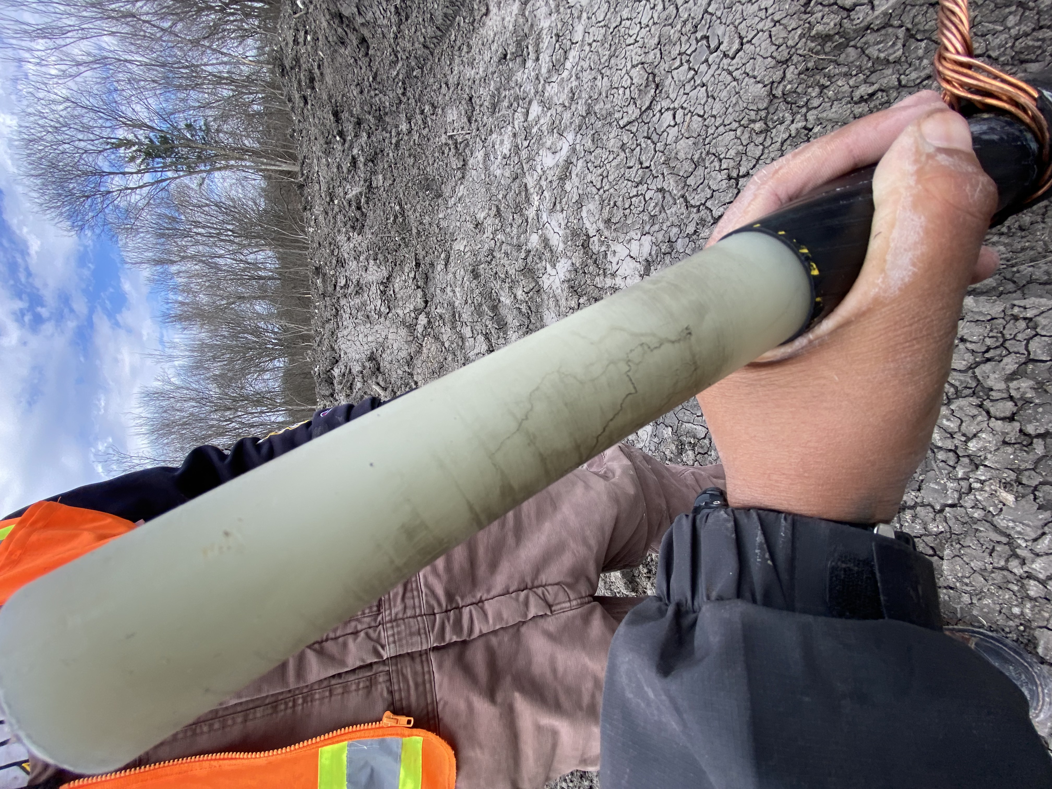
Figure 3 Electrical tree damage resulting from a passing VLF commissioning test.
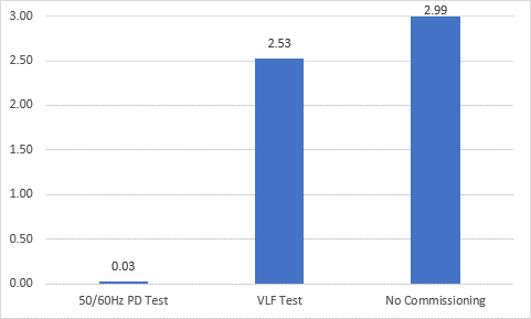
Figure 4 Post-commissioning failure rates per 100 miles per year
Conclusion
Although renewable energy and battery storage sites have more complex collector systems, they have the potential to rival conventional oil and gas plant performance. Both wind and solar technologies have undergone painful learning curves in terms of commissioning practices. With the adoption of well-established commissioning and maintenance best practices, the renewable energy sector and battery storage facilities are positioned to perform reliably for the foreseeable future.

Ben Lanz - Director, Strategy & Development – IMCORP With over 30 years in the power and energy industry, Ben Lanz is currently responsible for IMCORP’s technical outreach and education efforts and is the immediate past Chairman of the Board of the Power Delivery Intelligence Initiative (PDI2.org), a nonprofit dedicated to disseminating grid investment best practices. He is a senior member of IEEE PES and ICC, and a voting member of DEIS, IAS, ACP and CIGRE. He has chaired IEEE technical committees associated with power system reliability, protection, and testing, has published over 100 papers, articles and technical conference contributions on the subjects of power system reliability, asset management, design, work practices, longevity and diagnostics, and is a regular guest speaker at numerous conferences and seminars.
Chip Angus is Electric Reliability National Account Manager at SDMyers, LLC in Tallmadge, Ohio, where he specializes in helping industrial companies develop long-term transformer reliability solutions. Chip works primarily with manufacturing, steel, wind, solar, pulp and paper, and oil & gas customers by aligning their corporate reliability expectations with the realities at the plant operations level.
Chip presents at conferences across the U.S. as a resource in the field of industrial electric power reliability. He has been published in a variety of leading trade publications in the electric power reliability space. Before specializing in transformer management and electric power reliability, Chip was the president of Ryco Metals, a structural and plate fabrication firm and service center.

 Security in Substations")