Image for illustrative purposes
EGLA TECHNOLOGY
Externally Gapped Line Arresters (EGLA) are a solid-state technology comprising Metal Oxide Varistors (MOVs) to prevent lightning-induced outages on overhead lines. The high-voltage network industry in Japan pioneered the development of the first EGLA 40 years ago to address the unique needs of overhead lines. This was achieved by merging the distinct characteristics of MOVs with the advantages of air gaps. As early as 30 years ago, Japan had already installed more than 30,000 EGLA units in their network.
Although the technology has undergone significant improvements and widespread development globally, its full benefits are still underappreciated. MOV-based gapless surge arresters are internationally standardized for the protection of critical equipment, such as power transformers. However, their application in lines remains a subject of considerable debate. While some have mastered this technology, others are only beginning to explore its potential. Some uses, as we will see, go beyond protection against lightning but allow for ensuring optimal levels of safety with respect to people and equipment.
Although the [EGLA] technology has undergone significant improvements and widespread development globally, its full benefits are still underappreciated.
French TSO, Réseau de Transport d'Électricité (RTE), is contributing valuable insights to help us understand how EGLAs can address some of the most urgent challenges facing today's power grids, particularly in terms of safety and protection against lightning-induced network outages. Guided by RTE's unique expertise, this article aims to demystify EGLA technology, making it more accessible and comprehensible to a wide audience. By sharing extensive experience from RTE, the article illuminates the technical intricacies, safety protocols, and operational efficiencies of EGLAs. It targets a diverse readership, ranging from industry experts to policymakers, aiming to educate them on EGLA's untapped potential for enhancing grid reliability and safety. Discover why this technology could be the next significant advancement in high-voltage applications worldwide.
When did RTE first start using EGLA in its high voltage applications, and what was the main driving factor that motivated this adoption?
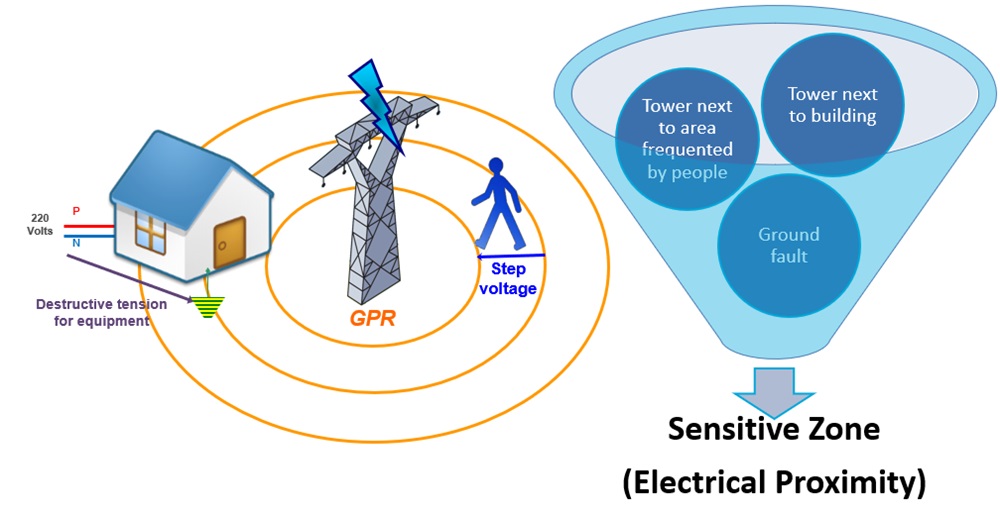
Toward the close of the 1990s, former TSO EDF (Électricité de France) had incorporated EGLA into all three phases of specific non-shielded towers. A primary concern at the time revolved around the flow of 50Hz fault currents into the earth following lightning flashovers. This becomes particularly problematic when towers are situated close to sensitive structures such as homes, schools, workshops, and markets. The flow of fault current into the ground results in a noticeable increase in the electrical potential of the surrounding soil. This poses risks to both electrical equipment grounded some distance from the tower and individuals either in contact with a grounded structure or moving in the tower's vicinity due to touch and step potentials. By employing EGLA, the follow current is interrupted post the drainage of the lightning impulse to the ground. As a result, there is an effective elimination of the 50Hz current flowing into the ground, preventing any rise in 50Hz ground potential.
By employing EGLA, the follow current is interrupted post the drainage of the lightning impulse to the ground. As a result, there is an effective elimination of the 50Hz current flowing into the ground, preventing any rise in 50Hz ground potential.
Can you briefly explain the primary differences between Externally Gapped Line Arresters (EGLA) and Non-Gapped Line Arresters (NGLA), and what led RTE to choose EGLA for its applications?
The fundamental distinction between EGLA and NGLA lies in the presence of the arcing gap. EGLAs are essentially Line Surge Arresters (LSAs) that are not perpetually exposed to the system voltage. Instead, their MOV modules only experience stress when a lightning impulse short-circuits the gap. This aspect plays a significant role in the aging process and overall reliability of EGLAs. Conversely, NGLAs are constantly exposed to the system voltage, making them responsive to any form of overvoltage occurring within the network. When designed appropriately, NGLAs offer comprehensive protection against various overvoltages, not just limiting themselves to lightning protection.
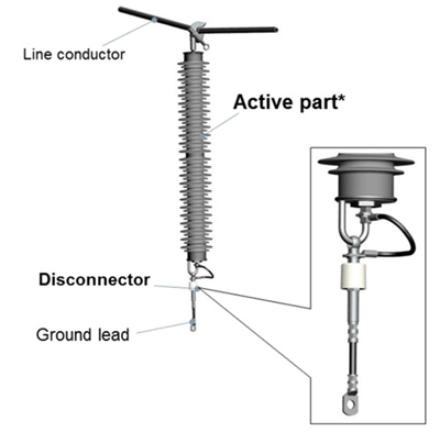
NGLA - Directly connected to power line
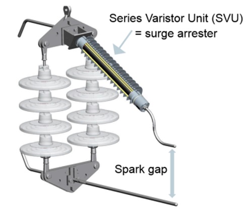
EGLA (1 SVU) - Isolated from power line through a series gap
NGLAs are constantly exposed to the system voltage, making them responsive to any form of overvoltage occurring within the network. When designed appropriately, NGLAs offer comprehensive protection against various overvoltages, not just limiting themselves to lightning protection.
How has the use of EGLA become standardized in France, while still being relatively misunderstood in other countries? What unique factors in France might explain this phenomenon?
As of 2023, France possesses a distinct setup wherein we stand as the sole TSO in France responsible for constructing, maintaining, and operating the High Voltage Power Transmission Network. This centralized approach greatly streamlines the standardization of assets and practices across the country. Although not the only factor, this centralization played a pivotal role in the widespread adoption of EGLA within France. From EGLA's inception, the primary challenge recognized was ensuring the insulation coordination among multiple air gaps: the EGLA's, the insulator strings', and the conductor's to the tower structure. To address this, we adopted a comprehensive approach where a full insulator string, complete with its arcing protections and the EGLA, is assembled. For any new EGLA installation, it isn't just the SVU (Series Varistor Unit) that's added; the entire set replaces the existing insulator string.
We've tailored EGLA sets to cater to various voltage levels, ranging from 63kV to 225kV. These are designed for both suspension and tension towers and can be installed without disrupting service, meaning there's no need for service interruptions when fitting a new EGLA string. This method proves advantageous as it minimizes the need for fresh conceptualizations with each installation, thus ensuring quicker deployment.
Addressing the latter is achieved through a diverse range of technical solutions tailored to each tower's specific environment. The incorporation of EGLA is merely one of these solutions, but it's one we've heavily invested in, refining it to be as "plug-and-play" as possible for our maintenance and engineering teams.
Could you elaborate on the safety concerns associated with EGLA in France? Why do these concerns seem more prevalent in France than in other countries?
It is important to note that LSAs are predominant worldwide for seeking to reduce network outages related to lightning. This is, of course, one of the uses in France, but the predominant reason for EGLA's usage is to mitigate the risks associated with ground potential rise due to lightning-induced faults. On one hand, post-WWII saw an exponential expansion of transmission line circuits, which originally were distanced from populated areas. Over time, these habitation zones grew closer to the transmission line towers. On the other hand, we have stringent internal regulations that prioritize the safety of the surroundings adjacent to our networks, encompassing both human safety and structural integrity. The heightened safety concerns in France stem from stringent domestic regulations aimed at ensuring that our electrical infrastructure does not compromise public safety. These regulations encompass a wide range of elements, including power lines, towers, cables, and substations. Safety criteria range from mitigating the risk of direct electrical shock to minimizing audible noise, radio interference, and ground potential rise, among other factors.
Are there any statistical data available regarding the failure rate of EGLA within RTE's operations? How does this compare to the global industry standards?
We haven't maintained specific statistics on EGLA failure rates within RTE’s operations, primarily because we have not encountered failures with our EGLAs. Therefore, we have not perceived a necessity to monitor this asset's performance closely. It would be speculative, yet educated, to assume that our EGLAs outperform certain NGLAs that have documented issues, such as failures in ground leads. However, quantitative data to substantiate this claim is currently lacking.
Can you explain how RTE manages to perform installation and maintenance of EGLA in live conditions? Is this practice common for all voltage levels within the network?
RTE executes live-line work for voltage networks ranging from 63kV to 400kV. However, EGLAs are not installed in the 400kV network for primarily two reasons:
-
The 400kV network experiences relatively fewer lightning-induced faults. Therefore, if EGLAs were to be implemented, their primary role would be to enhance the line's lightning performance and service reliability.
-
Our installation standards mandate that all EGLAs must be compatible with live-line work, or at least permit such work to be carried out in proximity to them. In this context, the SVU is treated as a live component as a conservative safety measure, impacting the safety distances considered during installation. This makes the design of a standard insulation string with an EGLA for the 400kV network more complex, although not technically unfeasible.
Currently, we are in the process of re-evaluating the need to include a 400kV EGLA in our asset catalogue. Future assessments will determine our course of action.
Were there any specific modifications made to RTE's EGLA design to facilitate live line working? If so, could you describe the changes that were made?
Indeed, while the concept is straightforward, its practical implementation poses challenges. Live line work mandates adherence to specific safety distances, particularly as the SVU is treated as a conductive element, akin to metal. To facilitate live line installation of our 225kV EGLA, predecessors in our team engineered a unique system. This system allows for the SVU unit to be installed without violating these safety zones. Specifically, the changes included installing the unit in a horizontal orientation, connecting it to an anchoring bar, and incorporating a pivot mechanism. This setup ensures that the EGLA is positioned at the precise distance required for the air gap.
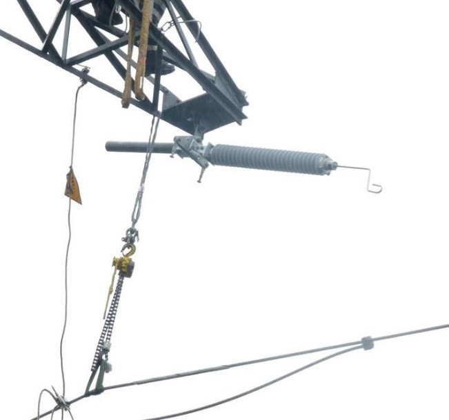
225kV EGLA – Installation in live conditions (1)
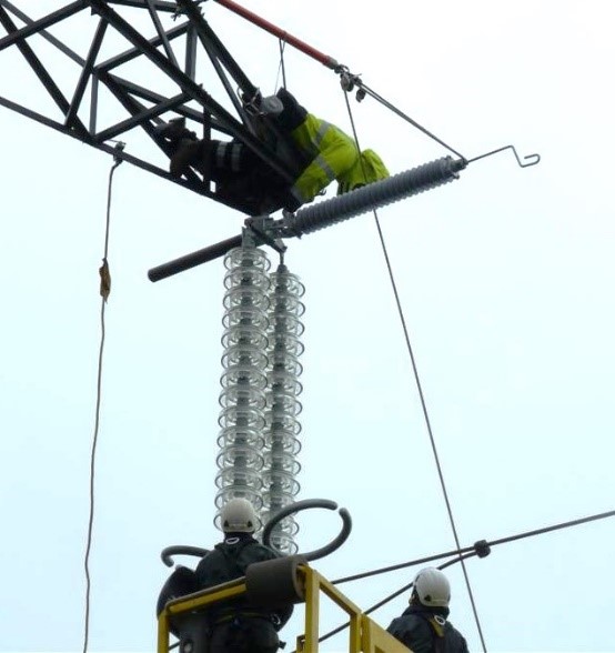
225kV EGLA – Installation in live conditions (2)
How does RTE’s experience with EGLA reflect the overall trends and development in the high-voltage industry in France and beyond?
Generally speaking, RTE's expertise in live line work is garnering recognition and is being adopted by multiple other TSOs. Additionally, it has come to my attention that EGLAs are under consideration in the United States to address ground potential rise risks near buried hydrocarbon metallic conduits.
Can you describe the typical lifecycle of an EGLA within RTE's network, from installation to replacement, and what maintenance strategies are employed to ensure optimal performance?
Upon receiving a request for EGLA installation, we proceed with the planning phase, during which we determine whether the line will remain in service or be taken off-service for the installation. For off-service installations, external contractors may be engaged to carry out the work. For in-service installations, each tower's requirements are meticulously planned by our specialized department. We do not rely on standardized live-work procedures; each tower is subject to its own unique analysis and strict adherence to safety distances.
Following installation, the EGLAs are generally low-maintenance. Our strategy consists of an annual visual inspection across all our lines. We employ a fault indicator system that activates a red flag when the SVU of the EGLA sustains damage. To date, this fault indicator has only been triggered in a laboratory setting and during one incident over a decade ago, which turned out to be a design failure rather than an issue with the SVU. Subsequently, the design was amended, and we have not experienced any false positives or negative reports of EGLA malfunctions since. Therefore, we have strong evidence to believe that both EGLAs and their associated fault indicators are performing as intended.
What are RTE's plans for the future of EGLA implementation, both in terms of technological advancements and strategic planning?
At present, we have adopted a new fault indicator technology from our existing EGLA manufacturer. While the operational principle is different, the end goal of fault detection is effectively achieved. Future installations of EGLA strings will be equipped with this advanced fault indicator. Moreover, we are currently assessing the demand for a 400kV EGLA solution.
Strategically, we are committed to advocating for the use of EGLAs to mitigate Ground Potential Risks. A key focus is on quantifying the actual risk reduction, which would make it more straightforward to select EGLAs as a cost-effective solution among various options. Additionally, we are promoting EGLAs to enhance the lightning performance of overhead lines that lack shield wires, which account for nearly half of our tower infrastructure.
At RTE, a full protection approach (every phase/every tower) of line sections is not our strategy; instead, we conduct detailed analyses to study various installation configurations tailored to the unique characteristics of each line. Our objective is to achieve optimal performance benefits at reduced costs, supported by feasible installation procedures. To facilitate this, we are continually refining our numerical models employed in Electromagnetic (EM) transient simulations.
Future installations of EGLA strings will be equipped with this advanced fault indicator. Moreover, we are currently assessing the demand for a 400kV EGLA solution.
How does RTE’s approach to EGLA align with France’s energy policies and regulatory landscape?
The deployment of EGLAs within RTE's network is particularly influenced by French legislative mandates that prioritize environmental protection in the vicinity of our towers, as noted earlier.
Can you share any interesting case studies or success stories related to EGLA's use in RTE's operations that might illustrate its effectiveness and benefits?
Certainly, we have several noteworthy cases. One involves a 225kV line located to the east of Paris, which was partially fitted with EGLAs on just one of its phases, specifically the section without a shield wire. As a result, the line's average yearly outage rate was reduced by 60%, going from one outage per year to 0.4 outages per year. Another example comes from the South of France, where we have a 225kV line running through a residential area with homes in close proximity, many of which have swimming pools. To mitigate potential risks, all phases of this line are equipped with EGLAs.
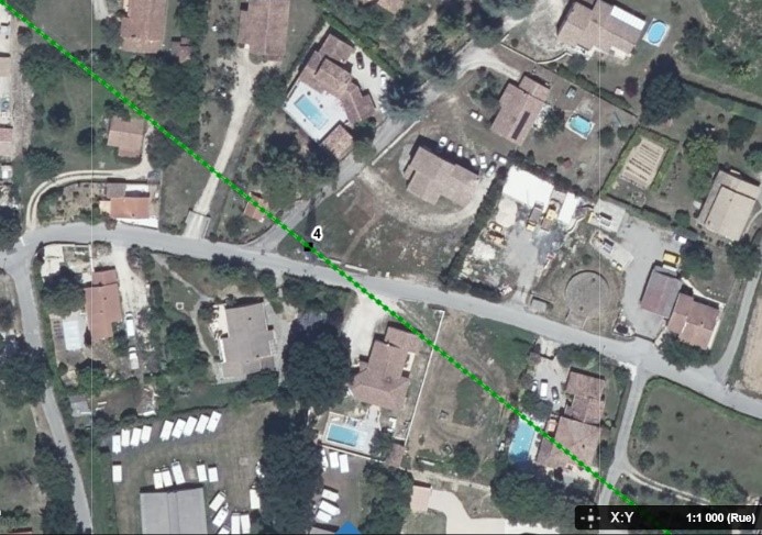
225kV Tower in the vicinity of residential considered as high risk – EGLA installed for safety concerns
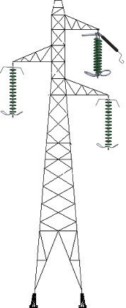
225kV EGLA on the top phase of an unshielded tower – lightning performance
What challenges, if any, has RTE faced in the implementation and maintenance of EGLA? How were these challenges overcome?
Challenges in the implementation and maintenance of EGLAs have largely revolved around fault indicators and establishing safe distances for live line installations of EGLA strings. While we haven't delved deeply into the topics of conception and qualification, they are crucial for ensuring appropriate insulation coordination for the air gaps. To meet these requirements, we have made multiple visits to laboratories for testing and modifications after the initial design phase, confirming the effectiveness of the string's design.
Finally, what advice would you offer to other utility providers considering the adoption of EGLA, especially those in countries where this technology is less understood?
It's crucial to understand that EGLAs are not subjected to continuous stress during service, making them highly reliable assets, particularly when Electromagnetic (EM) Transient studies are conducted to accurately determine their energy tolerances. Special attention should be paid during the qualification phase or pre-installation tests. Conduct tests that closely mirror actual installation conditions. While this approach may be time-consuming, it is a worthwhile investment to ensure you're implementing a technology designed to provide reliable service for several decades.
In summary, the potential for improving lightning performance through the use of EGLAs cannot be overstated. Modern advancements in surge arrester technology, particularly in the area of EGLAs, pave the way for minimizing the risks associated with lightning strikes on power systems. The reduction in flashover rates, coupled with enhanced system reliability, underscores the value these devices bring to the electricity supply industry. However, it is crucial to consider these benefits within the context of safety concerns that could affect both equipment and personnel.
The deployment of EGLAs must adhere to rigorous safety protocols, especially during live line installations. It is imperative that best practices be followed in the selection, installation, and maintenance of EGLAs to fully leverage their potential while also mitigating risks.
Looking beyond mere lightning performance and safety, EGLAs hold promise for various other applications. They could be adapted for use in line compaction, retrofit applications, and enhanced power corridors—developments that are increasingly essential in the context of energy transition.
In conclusion, EGLAs serve as a beacon of innovation, offering significant improvements in both lightning performance and system reliability. However, they must be carefully integrated into power systems with keen attention to safety standards, affecting both human and material resources. As we move forward, the application of EGLAs in broader contexts reveals a bright future, replete with opportunities for further advancements and implementations.
EGLAs serve as a beacon of innovation, offering significant improvements in both lightning performance and system reliability. However, they must be carefully integrated into power systems with keen attention to safety standards, affecting both human and material resources.

Luis Diaz is an R&D Engineer at the National Center of Expertise for the French Transmission System Operator (TSO), RTE. He holds an MSc Degree in Electrical Engineering from the Simon Bolivar University in Caracas, Venezuela, and a PhD through a CIFRE program in collaboration with EDF R&D and the University of Limoges, France. His expertise lies in Lightning Protection and Insulation Coordination of Power Systems, encompassing both underground and overhead systems. At RTE, Luis is entrusted with drafting technical specifications for composite insulators and overhead line (OHL) surge arresters. He offers expert guidance to both the engineering and maintenance divisions, tackling intricate challenges in lightning protection systems and insulation coordination. Furthermore, he spearheads modifications to the national maintenance policy, aiming to diminish electrical risks to third parties. Luis represents RTE and France in the B2 and C4 CIGRE committees, as well as in the TC36 and TC37 IEC Committees.