
TECHNOLOGY INSIGHTS by Corné Dames
In her new article, Corné Dames focuses on the types of tests to determine the condition of the transformer, outlining the critical values and the recommended actions.
Condition monitoring is the frequent collecting, measuring, recording, and analysis of relevant data. If we interpret the data correctly, it can give us great insight into the condition of an asset.
This frequent monitoring of a transformer can result in less maintenance required, or more extended periods without any maintenance required at all.
It is crucial to identify the key parameters that are needed to give us a complete picture of the actual status of the transformer and the actions we need to take to ensure the continued reliability of the transformer to achieve and maximize its life cycle.
What is the data telling us?
-
Has the condition of the unit changed since the last maintenance or testing period?
-
Is it safe to operate the unit?
-
Are there signs of deterioration?
-
Is it safe to load the unit above the nameplate rating for some period?
-
Am I required to implement action to ensure the continued reliability of the unit?
-
How long can we use the unit before considering replacement?
-
Are the identified problems of a recurring nature?
It is vitally important to identify clear goals as part of your transformer monitoring strategy.
Effective condition monitoring outline
It is vitally important to identify clear goals as part of your transformer monitoring strategy. What do you want to achieve by implementing this condition-monitoring plan? Is it in-service failure prevention, life extension or maintenance deferral? By stipulating the outcome and what you want to accomplish, it would be much easier to identify the required parameters.
Health indexing of assets is becoming an important tool to obtain a clearer picture of the condition of your transformer. Test parameters carry a numerical value-adding to the total value of the Health Index Value of the transformer. These parameter weight values were calculated based on the international standards for mineral oils, indicating the critical values stipulated in the various standards.
The scope of oil analysis, interpretation of the data and critical values
It is important to realize that we deal with different size transformers in the industry, where transformers are divided into classes according to the kV ratings of the equipment (see Table 1 [1]). It is up to the reliability or asset manager to use the guidelines for larger equipment, thereby implementing shorter increments of oil analysis and electrical testing. Table 2 explains which oil analyses are recommended, how often or under which circumstances [1].
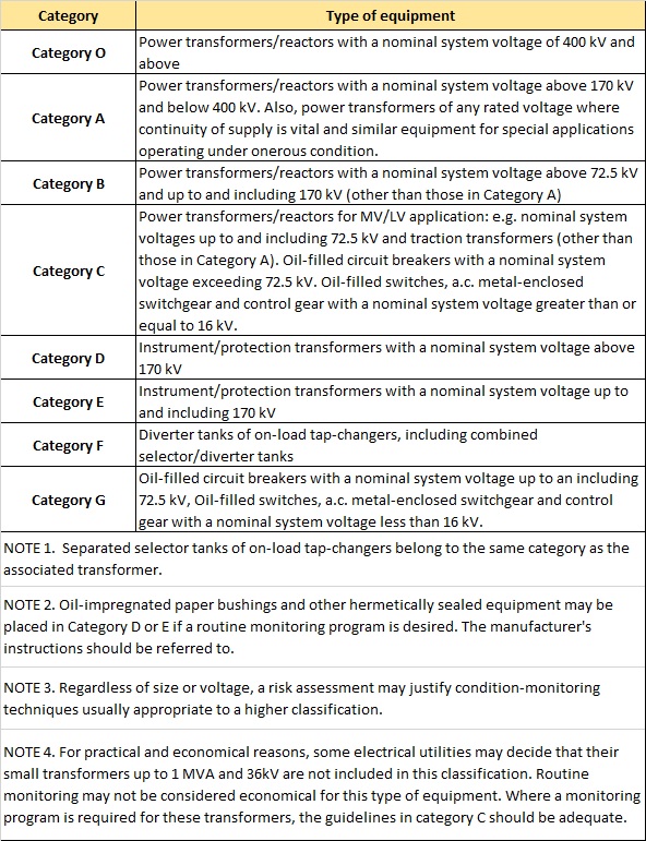 Table 1. Equipment categories [1]
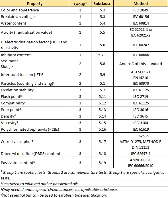 Table 2. Tests for in-service mineral insulating oil oils [1]
Color and appearance
This is a routine inspection applied to every oil sample. When an oil sample arrives at the laboratory, one of the “tests” is a visual inspection of the oil sample in a clear vessel to determine the color, turbidity and possible particle identification.
Dark oils might indicate chemical degradation or contamination of the oil. When there is a lot of turbidity, it might indicate high-water content in the oil.
If the drain valve was not wiped clean by the sampler, the dirt particles in the drain valve might be incorporated into the sample. If particles are identified as carbon, this might indicate a possible electrical fault in the unit. The DGA analysis of the oil will confirm if this is the case.
Clear oils without contamination will indicate a good condition, and no action is recommended.
When oils are dark or turbid, further analysis will confirm if there are any problems. The oil analysis results will also determine the degree and type of action.
Breakdown voltage
This is a routine inspection.
Breakdown voltage (Table 3) will indicate the water content or the presence of foreign particles, or both in the oil being analyzed. As the oil in transformers acts as an insulation medium to avoid flashover in the unit, the breakdown voltage must be high.
If the values are Good, it is recommended to continue with the current sample interval action plan.
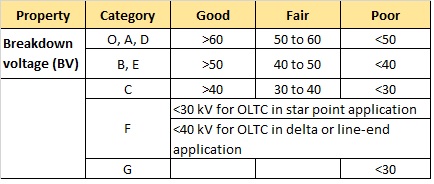
Table 3. Breakdown voltage test
If the values are Fair, more frequent sampling is recommended in collaboration with other parameter results like the water content, DDF, and acidity. If values are Poor, it is recommended to recondition the oil via oil reconditioning processes.
If alternative tests indicate severe aging, the oil can be replaced with new or reclaimed oil. Another option would be to perform on-site reclamation of the oil using a reclamation plant.
Reclamation of oil has the advantage that the color of the oil is restored, and the polar components are removed from the oil. This process will remove acid and water as well as some other compounds. Another advantage is that the oil can be re-used, and in most situations, this can be done without switching off the unit, which contributes to cost-saving. If in doubt – switch off the unit during this treatment process.
If the values are Poor, it is advisable to take action as soon as possible and not delay the maintenance process. Excess water in the transformer system decreases the projected transformer lifetime significantly; extremely high water content can cause flashover in the unit resulting in loss of the asset.
Water content (mg/kg at transformer operating temperature)
This is a routine test for all classes of electrical equipment, except class G (Table 4). The results of this test should always be considered in collaboration with the breakdown strength.
If it is found that the water content is high and the breakdown strength is low, further action needs to be taken. It is recommended that a second sample from the same unit is tested to confirm the results.
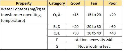
Table 4. Water content test
In the case of switching equipment, where there is no paper present, the breakdown voltage is the determining factor.
It should be noted that the limits indicated by IEC 60422 Edition 4 [1] apply to transformers with operating temperatures between 40 and 70°C. If it is found that the unit's operating temperature is outside this temperature range, it is best to refer to Annex A of the standard.
When the value obtained through analyses is Good, the normal sampling interval can be maintained, requiring no further action.
When the value returns a Fair result, more frequent sampling is recommended. It is also helpful to consider other parameters like the breakdown voltage, particle content and DDF/resistivity, and acidity to decide the action to be implemented.
A Poor result will require immediate action from the asset manager. This might include taking another sample to confirm the results from the first analysis. If it is confirmed that the water content is high, the oil should be filtered; a process that can remove a large portion of the moisture from the oil if applied correctly. (Editor’s Note: It is recommended that passive drying over a prolonged period of time is a better solution than filtering, since there is more moisture in the paper than in the oil.)
Follow-up samples need to be taken to ensure that the moisture content is still within the required limits. The reason is that the most significant portion of the water is caught up in the paper system in the transformer. This moisture will move from the paper into the oil under conditions that favor this movement. It might be found later that the oil in the water has increased again without any apparent reason, but the source would be the paper in the transformer.
A visual inspection is also recommended to determine if any water might move into the transformer or electrical equipment through leaks. This problem might be more severe if the transformer or electrical equipment is outside and not in a covered area.
Acidity (mgKOH/g oil) neutralization number
This is a routine test for all classes except F and G (Table 5).
The acids in oils are formed due to chemical reactions between the oil, water, and paper. Higher temperatures or increased load will increase the formation of these acids. Because acids are polar compounds, it will adversely affect the insulation properties of the oil and will increase paper degradation. If left untreated in transformers, this can lead to sludge formation, usually around the lower parts of the transformer core. The sludge will eventually form a semi-solid substance that is extremely difficult to remove.
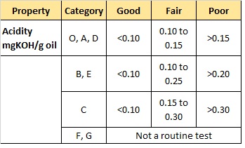
Table 5. Acidity test
If the result is Good, the regular sampling interval can continue. In case of a Fair result, the sampling interval should be increased to fit the situation. Future analysis should include a visual inspection of the oil for sediment and sludge. If the result is Poor according to the prescribed values in IEC 60422 Edition 4.0 [1], the asset manager may decide to reclaim the oil or replace it with new or reclaimed oil, whichever option might suit their requirements the best.
Dielectric dissipation factor at 40 Hz to 60 Hz at 90°C
This is a routine test for all classes of electrical equipment, except F and G (Table 6).
The dielectric dissipation factor or tan delta test provides information regarding the extent of the dielectric losses in transformer oil. This test measures the inefficiency of insulating material.
When oil ages, we have the formation of polar compounds, leading to phase displacement and dielectric losses. Some other impurities that might influence the dissipation factor include water, dissolved insulating resin, and paper. When the result is Fair, more frequent sampling and checking additional parameters is recommended. When the result is Poor, reclamation or an oil change is recommended.
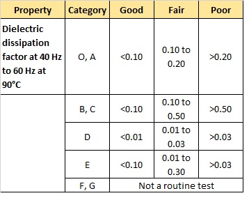
Table 6. Dielectric dissipation factor test
Resistivity (GΩm) at 20°C or 90°C
This is NOT a routine test (Table 7). DC resistivity of the oil is one of the key parameters to assess the transformer insulation condition; this is based on the fact that DC resistance is sensitive to oil degradation.
When the result is Fair, more frequent sampling and checking additional parameters is recommended. When the result is Poor, reclamation or an oil change is recommended.
Inhibitor content %
This test is restricted to oils with inhibitor added (Table 8). It would be advisable to contact the oil supplier to verify the details regarding additives.
The two most common oxidation inhibitors for transformer oils are 2,6-di-tertiary-butyl para-cresol (DBPC) and 2,6-di-tertiary butyl-phenol (DBP). The purpose of the inhibitor is to prevent oxygen from reacting with the oil. This significantly slows the aging process in the oil as well as in the solid insulation.
If the result is Fair, it is advised to top up the inhibitor level to the prescribed level per supplier instructions. It is advisable to use a field professional trained in the procedure to perform this task.
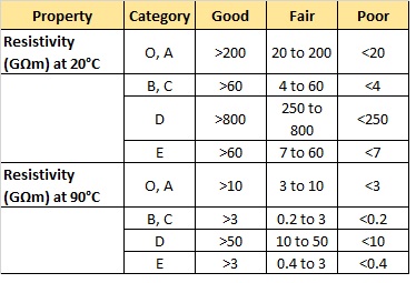
Table 7. Resistivity test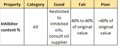 Table 8. Inhibitor content test
Passivator content
Passivators, also known as metal deactivators, react with reactive metal surfaces and dissolved metals such as copper and silver and reduce their rate of reaction with compounds in the oil. This includes oxidation reactions with organic compounds and reactions with corrosive sulfur. Passivators are composed of two basic types: sulfur-based and nitrogen-based. The first suggested use of passivators in transformer oil, which the author is aware of, was in 1967 by J.J. Melchiore and I.W. Mills of the Sun Oil Company [3].
As the oil ages, the passivator might deplete more rapidly; this depletion might accelerate when the oil is un-inhibited.
With Good results, regular sample intervals can be maintained (Table 9). With Fair results, maintain regular monitoring. When the results are Poor, it is advised to remove the oil or remove the source of corrosivity from the oil via special oil treatment.
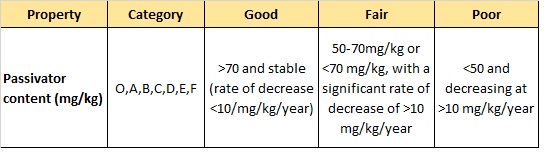 Table 9. Passivator content test
Sediment and sludge
This is not a routine test. It is advised that this test is performed when the oil results indicate a high acid value and the dissipation factor is near the acceptable limit.
The results need to be less than 0.02% by mass to be negligible. If the results return a value of more than 0.02% by mass, it is suggested that it be reclaimed. Otherwise, an oil change is recommended.
Interfacial tension
This is not a routine test (Table 10).
During the aging process, the interfacial tension between transformer oil and water reduces. What this means in practical terms is there is more polar compound present in the oil, decreasing the ability of an oil to serve as an insulator in the transformer system. There is a direct correlation between interfacial tension and neutralization number. Therefore, the interfacial tension becomes a quality criterion: the oil must be changed below a predefined limit.
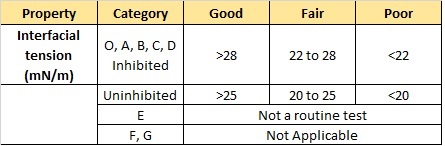
Table 10. Interfacial tension test
If the results are Good, continue the regular sampling interval. If the results are Fair, increase the sampling interval. If the results are Poor, Check the oil for sediment and/or sludge.
Corrosive sulfur
This is not a routine test.
Oil is either corrosive or non-corrosive. The presence of corrosive sulfur in transformer oil and its effect on the transformer system can be significant. The extent of the corrosion damage caused by the sulfur can be so severe that it might cause the failure of the equipment if not checked. The addition of a copper passivator can reduce the impact of this compound on the transformer system.
CIGRE Brochure no. 378, 2009 stipulates the necessity of corrective actions based on this institute's risk assessment study [4].
Particles counting and sizing
Table 11 outlines typical contamination levels (particles) encountered on power transformer insulating oil as measured using IEC 60970 [5].
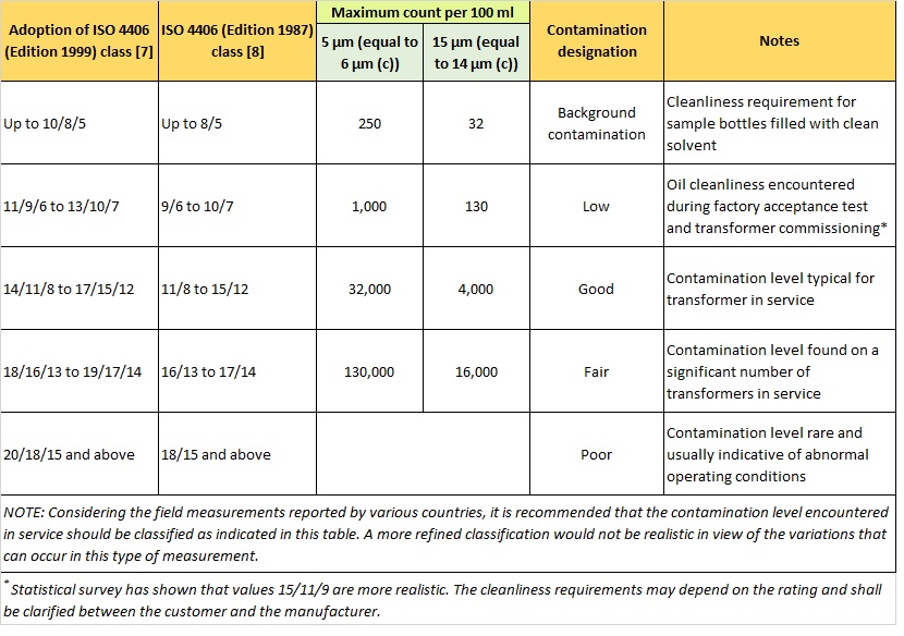 Table 11. Typical contamination levels (particles) encountered on transformer insulating oil as measured using IEC 60970 [5]. Source: CIGRE Technical Brochure 157, June 2004 [6]
Flashpoint °C
This is not a routine test.
If there is a maximum decrease in flashpoints by 10%, the equipment might require further inspection. This value might differ in different countries.
It is advised to perform this test when an unusual odor is noticed, the unit has been refilled, or an internal fault has occurred.
PCB
This test is not to determine the condition of the transformer. It is a health and safety impact test. PCB is hazardous to both humans and the environment, and it is therefore vital to test for PCBs after the retrofill of a transformer. The test is also required whenever any maintenance has been done on the unit and the possibility of contamination is present. If PCB content is exceeding the recommended limits, the appropriate action needs to be taken.
The limits are defined by local regulatory bodies.
DGA
As DGA (Dissolved Gas in Oil) is an intricate science with a lot of data and interpretation, we will discuss this phenomenon in part II of the article. The limits for the different gases and the interpretation of this data according to international standards will be discussed in detail, forming part of the overall health rating determination of the transformer.
Conclusion
This is an interlaced, highly exciting field of study. In this article, we focused on the types of tests to determine the condition of the transformer, the critical values, and the recommended actions. In the future articles, we will focus on determining the Health Index for each unit using the test data results and each test's weight in the Health Index determination.
The Health Index indication will make it possible to see the supposed reliability of a specific unit at that specific date and time. This will make it possible to ensure best practice application and optimized maintenance. With this information, it would be easier to draw up a maintenance plan and action plan.
References:
1. IEC 60422 Edition 4.0 2013-01 International Standard, Mineral insulating oils in electrical equipment – Supervision and maintenance guide
2. A. Shkolnik, “Oxidation inhibitor and reinhabiting oil-filled transformers”
3. L. Lewand, Passivators, “What They Are and How They Work,” Doble Engineering Company
4. CIGRE technical brochure 378, 2009, Copper sulfide in Transformer Insulation
5. IEC 60970:2007, Insulating liquids - Methods for counting and sizing particles
6. CIGRE Technical Brochure 157, 2000, Effect of particles on transformer dielectric strength
7. ISO 4406:1999, Hydraulic fluid power — Fluids — Method for coding the level of contamination by solid particles
8. ISO 4406:1987, Hydraulic fluid power — Fluids — Method for coding level of contamination by solid particles

Corné Dames
Corné Dames is the Managing Director of Independent Transformer Consultants, always striving to keep on top of new developments and research. She has expertise as Laboratory Manager in the analysis of transformer oils and as diagnostician identifying problem areas in transformers, as well as profiling of transformers according to available results thus empowering the customer to take preventative steps in maintenance. Corné has vast practical and theoretical knowledge on reliability maintenance programs. Coming from a strong chemical background she has insight in all the chemical processes that is part of the transformer system coupled with technical insight helps customers optimize their reliability maintenance and electrical asset lifetime.