Photo Credit: Huaming
EXPERIMENTAL STUDY
1. Experiment Design:
Transformers are essential equipment in electric power transmission. In order to ensure the stable operation of transformers and prevent power supply failures due to foreseeable factors in the power system, the smooth operation of the on-load tap changer, which constitutes a vital part of transformers, will mitigate operational risks in the system.
To quantitatively analyze the gases that influence the safe operation of transformers during the functioning of on-load tap changers, a comprehensive set of experimental procedures has been devised.
1.Developed a dedicated experimental platform to facilitate the installation of on-load tap changers and subsequent gas generation tests.
2.Provided a customized large oil tank to immerse the OLTC.
3.Configured a complete set of power frequency withstand voltage testing equipment.
4.Designed a special funnel for gas collection during experimentation.
5.Equipped with motor drive for driving the switch mechanism.
6.Implemented a set of real-time monitoring devices, including Tektronix oscilloscopes, infrared thermal imaging cameras, surveillance cameras, high-speed cameras, multimeters, and real-time voltage monitoring devices at the voltage output terminal.
7.Customized an experimental-specific gas collection bottle, constructed of glass and featuring a three-way valve and a unidirectional valve, along with accessory pipelines for metering purposes.
Position the experimental fixture above the oil tank, and fix the funnel onto the test switch via mounting plates. Then mount the switch onto the experimental platform. After adjusting the voltage divider resistors and inductance, connect the generator and the circuit by conductors. Following this, the output of the voltage divider is led to the positive and negative terminals of the tap selector. Thereafter, after filling the insulating oil into the tank, fasten the measuring device onto the calibration fixture for experimentation using 3D-printed mounting sleeves and adhesive onto the test platform.
2. Gas Generation Location
2.1 Equipment Contact System Types
The gas generation position prone to arcing in the on-load tap changer is typically located at the contact points. The contact system is critical for tap changer, designed to carry current, make and break circuits. It functions as an executor within the tap changer assembly. Generally, tap changers can be categorized into two major types based on their operational tasks: load current carrying contacts and arc contacts. Typically, the contact system of the tap selector is designed according to its current-carrying capacity, thus forming a set of load current contacts. On the other hand, the contact system of the diverter switch manages the carrying and transition of load current, including the main contacts and inter-connecting contacts. Another set of contacts is composed of refractory materials to mitigate intense oxidation reactions (combustion) on metal surfaces during arcing and endure the wear that occurs during the making/breaking process.
2.2 Experimental Equipment Configuration
In this case, the arcing gas generation primarily occurs at the change-over selector's moving contact position. The structural design of the experimental equipment for this study is in the shape of "T" and adopts a single-axis design. A single-axis design refers to an insulated shaft, upon which a rotating arm is situated within the cage, allowing this insulated rotary shaft to rotate (incrementally) in order to bring the moving and fixed contacts into making/breaking. The structure is depicted in the Figure 10.
Figure 1: Contact Structure
This structure is widely utilized in various types of tap changers.
3. Determination of Experimental Platform and Experimental Scheme
During the experimentation process, the test object are immersed in container filled with transformer oil and placed in a specially designed thermostatic chamber. It is to simulate typical dielectric partial discharges within the transformer by applying power frequency voltage. The simulation system for transformer partial discharge is illustrated in Figure 9.
Among these components, the material primarily utilized for the simulated oil tank is acrylic, with dimensions of Φ1,900mm (diameter) × 2,970mm (height). The thermostatic chamber, which utilizes the existing electrical testing lab of the factory, occupies an area of 3,000,000mm (length) × 200,000mm (width) × 100,000mm (height), as depicted in Figure 7. The characteristics of this simulation system are as follows:
a) Temperature Monitoring of the Tap Changer — Due to the non-uniform temperature distribution within the simulated oil tank, the temperature of the upper oil part is higher than that of the lower part. Additionally, the temperatures of various components and the oil will undergo changes upon polarity change-over of the tap changer. To address these variations, a temperature monitoring apparatus is set up. The temperature monitoring provides the following two benefits:
1. In the power frequency withstand voltage testing, the resistors and voltage dividers in the circuit will bear a load. Consequently, the components’ temperature will increase rapidly with the number of switching operations. Given that the resistance endurance temperature is approximately 250°C and the extreme limit temperature is 300°C, temperature monitoring is established to promptly stop the experiment, thus preventing aging and damage to components.
2.Although there is non-uniformity in the upper and lower oil temperatures within the barrel, the oil temperature affects gas solubility. Excessively high oil temperatures close to the boiling point can raise certain issues. Monitoring in real time is essential to avoid such problems.
b. Remote motor drive Control Device — The tested on-load tap changer, while energized, employs a remote control device to rotate the tap changer from safe distance, preventing unnecessary personnel accidents.
Figure 2: Motor drive unit model SHM-X
c. Oil Sampling — To facilitate the analysis of dissolved gases in transformer oil, a specialized collection apparatus utilizing an ultra-irregular funnel design was devised. This apparatus is connected to a customized, pressure-resistant oil pipe that links to a precisely calibrated glass measurement cup fitted with a customized burst-proof double-headed unidirectional valve.
3.1 Partial Discharge Measurement and Acquisition System
-
Partial Discharge Wiring
Basic test circuits for measuring partial discharges are generally categorized into two major types: direct circuits and bridge (balanced) test circuits. Direct test circuits are further subdivided into parallel test circuits and series test circuits. In this study, a series test circuit is employed due to its sensitivity enhancement with the increase of the coupling capacitance CK to the sample capacitance CX ratio.
The experimental wiring for the partial discharge model is illustrated in Figure 9. The test power supply consists of an auto-transformer T1 and a power frequency non-partial discharge test voltage divider C2. Its rated voltage is 300 kV, and its rated capacitance is 1000 pF. The transformer's rated capacity is 1200 kVA, and the voltage is limited to a maximum of 35 kV under the prescribed transformer operating conditions. The limiting current resistor serves to restrict the voltage, providing protection to the experimental setup in the event of test specimen breakdown.
The coupling capacitor C1 has a capacitance value of 4000 pF and can withstand a voltage of 66/√3 kV. It acts as a coupling device in the partial discharge circuit and is parallel-connected externally to a resistive-capacitive voltage divider, which has a resistance value of 60.76 mΩ and a capacitance value of 598.8 pF. This component simultaneously functions as a voltage divider during the test, allowing for phase correction of the partial discharge waveform. The oscilloscope is connected in parallel to both ends of the resistive-capacitive voltage divider, serving as the monitoring unit for the partial discharge signal. It measures the partial discharge signal, displays, captures, and stores the signal waveform. SW1 represents the partial discharge model within the on-load tap changer polarity switching in the transformer. This component is positioned within a specially designed simulated oil tank to replicate the operational status of the on-load tap changer in the transformer.
Figure 3: Test Circuit
-
Experimental Procedure:
Begin by filling the oil tank with an adequate amount of oil. Install the specialized funnel onto the contact terminals on the change-over selector of the on-load tap changer for HVDC converter transformer. Connect the pipeline and secure the pipeline head to the head flange using zip ties to ensure the pipeline is vertically aligned. Proceed to install the OLTC onto the experimental frame. Subsequently, position the frame with the installed switch over the oil tank, allowing the oil inside the tank to just submerge the specialized funnel and ensuring the gas collection device's seal. Then, mount the gas collection apparatus at the designated hole on the installation frame and connect the pipelines at each valve port. Following this, install the motorized mechanism on the experimental frame. Finally, connect the test circuit to the OLTC to commence the measurement.
Experimental Results:
In this experiment, a comparative trial was conducted with the fast contact assembly and detachment methods. Each comparative trial adhered to the following standards:
The motor drive mechanism was rotated 1800 times, the polarity contacts were switched 900 times (counting method as indicated in the diagram), and the load voltage for power frequency withstand voltage was set at 36 kV.
Wherein, with the installation of the fast contact assembly, approximately 14 ml of gas was collected, and the effective components are illustrated in the figure below:
Table 1: Transformer Oil DGA Testing Report
Upon detachment of the fast contact assembly, approximately 25 ml of gas was collected, with the effective components illustrated in the figure on the right:
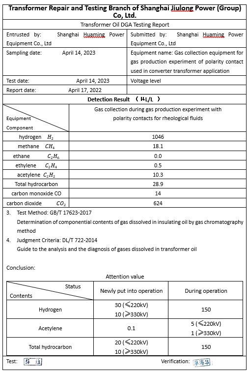
Table 2: Transformer Oil DGA Testing Report
In the experiment, the moment of contact discharge and bubble generation was captured using a high-speed camera.
1.Installation of Fast Contact Assembly Above the Tap Changer's Polarity Contacts:
1.1 When the tap changer performs polarity switching between the contact boards, the moving contact is brought into contact with the fixed contact by the main shaft. At this moment, the discharge phenomenon as shown in the figure below can be observed.
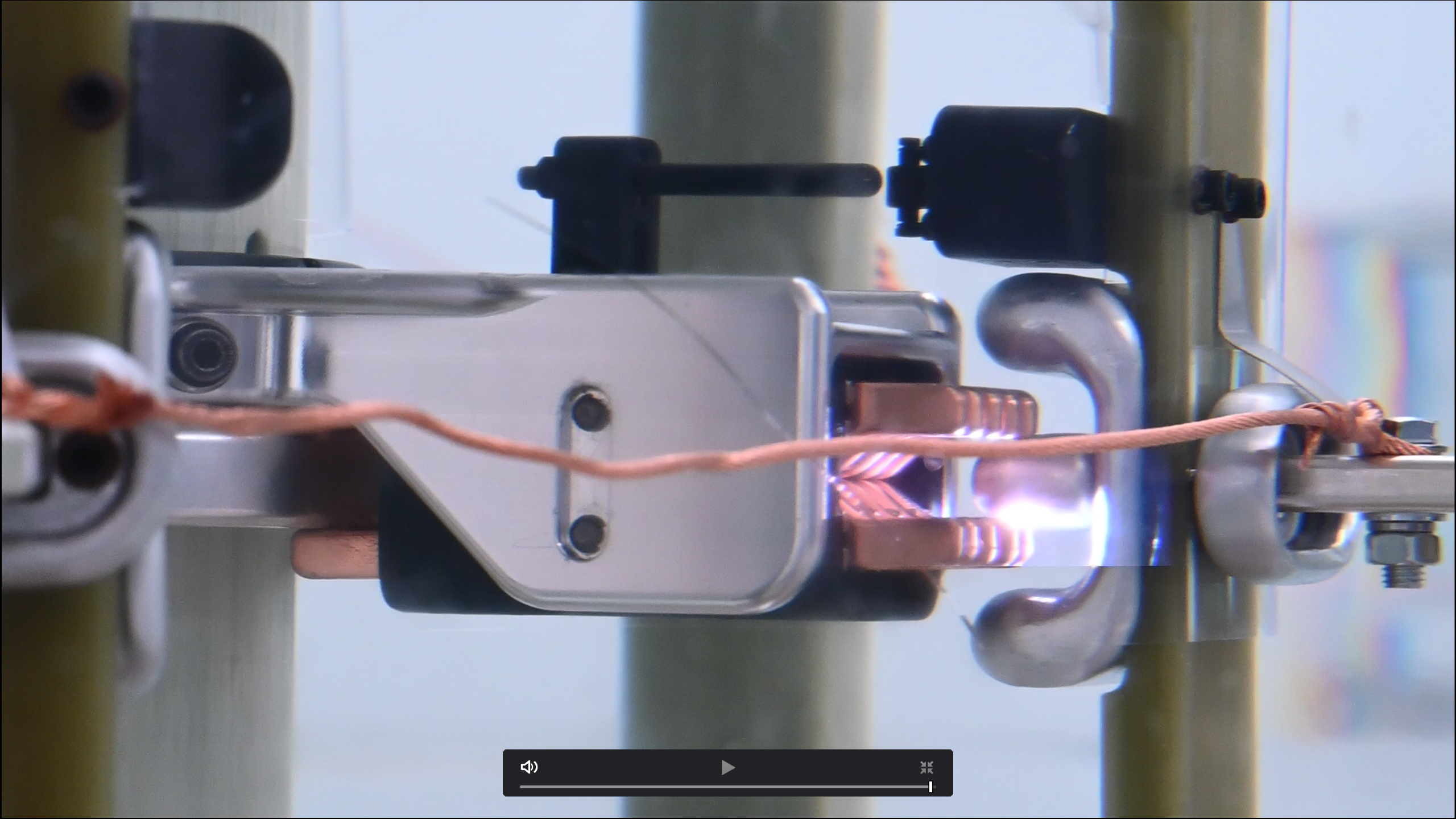
Figure 4: Discharge phenomenon when the tap changer performs polarity switching between the contact boards,
-
Remove the Fast Contact Assembly Above the Tap Changer's change-over Contacts:
2.1 When the tap changer performs polarity switching between the contact bars, the moving contact is brought into contact with the fixed contact by the main shaft. At this moment, the discharge phenomenon as shown in the figure below can be observed.

Figure 6: Discharge phenomenon when the tap changer performs polarity switching between the contact bars
1.2 When the tap changer performs reverse polarity switching between the contact bars, the moving contact is detached from the fixed contact by the main shaft. The fast contact assembly replaces the main contact and rapidly disengages from the contactor. At this moment, the discharge phenomenon as shown in the figure below can be observed.
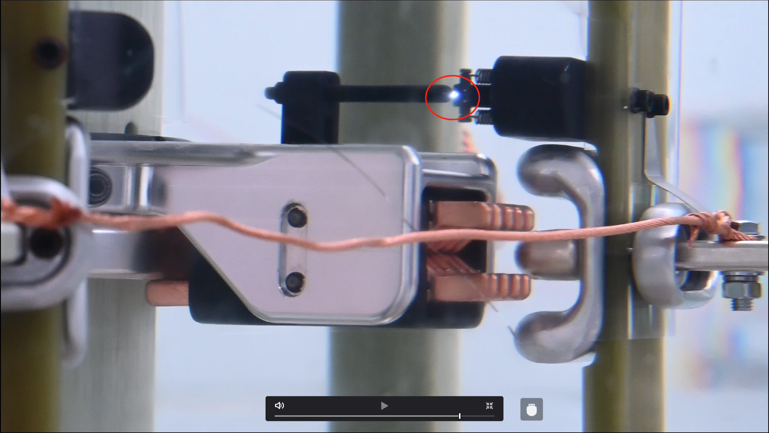
Figure 5: Discharge phenomenon when the tap changer performs reverse polarity switching between the contact bars
2.2 When the tap changer performs a change-over switching in reverse phase between the contact bars, the moving contact will be detached from the fixed contact driven by the main shaft. The discharge phenomenon as shown in the following figure can be observed.

Figure 7: Discharge phenomenon when the tap changer performs a change-over switching in reverse phase between the contact bars
Waveform collected through oscilloscope during polarity switching: Circuit voltage in the typical test circuit:
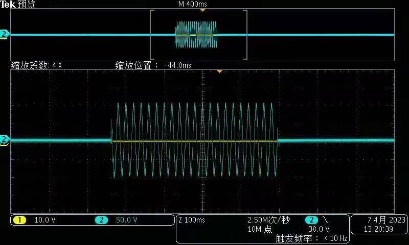
Figure 8: Waveform collected through oscilloscope during polarity switching
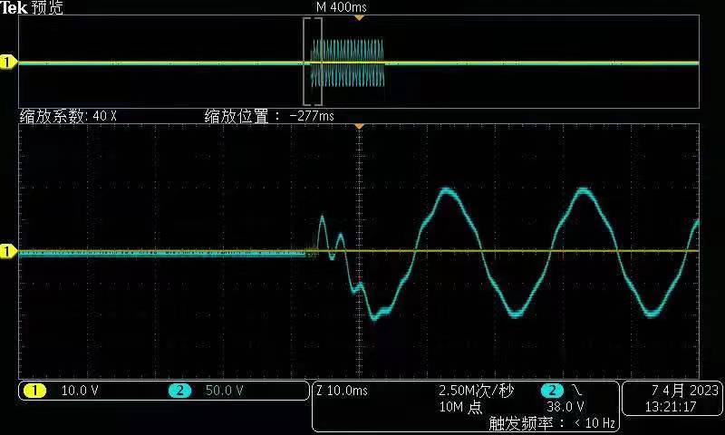
Figure 9: Waveform of Head and Tail Oscillation During Contact Separation -1
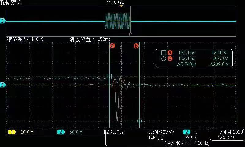
Figure 10: Waveform of Head and Tail Oscillation During Contact Separation -2
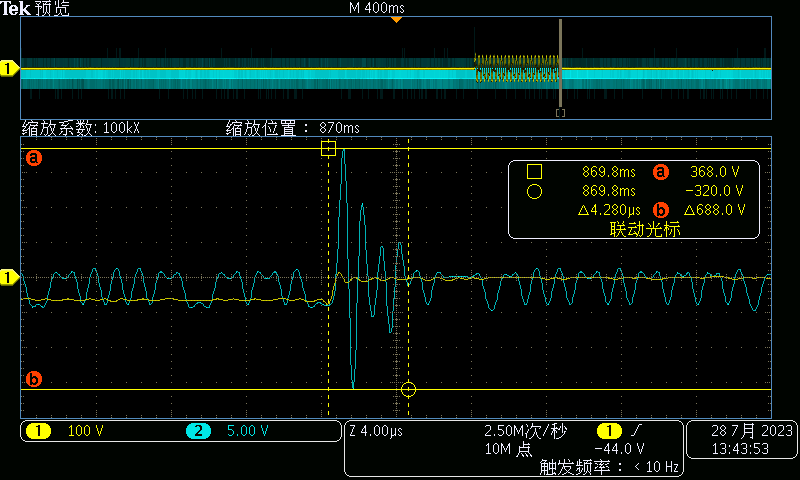
Figure 11: Waveform of Head and Tail Oscillation During Contact Separation -3
Grounding Terminal Discharge Waveform (This waveform is unstable)
5. Experimental Conclusions
Through the gas generation experiment, we have observed that in mineral insulating oil, discharges are inevitable during each tap change of the change-over contacts. Discharges induce subtle ionization reactions within the insulating oil, which are proportional to the contact's conductive cross-sectional area. The designed fast contact assembly method, due to its delayed disconnection and smaller conducting area, effectively suppresses the discharge quantity, thereby reducing the gas generation from the polarity contacts. This approach significantly prolongs the inspection interval of the switch.
Across multiple trials, we have noted that although gas generation is positively correlated with applied voltage, the operational role of the on-load tap changer in a transformer primarily regulates voltage, thereby implying that the number of switches better reflects gas generation under actual operational conditions. Within this experiment, it is observed that, without any gas generation suppression measures, the switch needs to be operated approximately 36 times to produce 1 ml of gas. Considering that the gas volume warning threshold for on-load tap changers is around 250 ml, protection relays capable of monitoring gas volume are sufficient to mitigate the impact of gas over decades of switch operation in power transmission and transformation scenarios. However, for cases of frequent switching, considering voltage levels and switching frequencies, additional gas generation suppression devices should be employed to extend the operational lifespan of on-load tap changers. With regard to this gas generation and quantitative experiments, it offers limited benefits to existing OLTCs. But it proves the gas suppression design, validated through experimentation, is effective. This structure utilizes an active spring mechanism in conjunction with ultra-fine contact heads to artificially reduce the contact area, thus rendering the conditions for arc breakdown more stringent. The spring's rebound results in rapid separation, achieving fast arc extinguishing. While proven effective in experiments, this structure fails to function during reverse phase switching, compromising its gas generation suppression effectiveness.

Guan Sijia started with Shanghai Huaming Power Equipment Co., Ltd. As an engineer for product research and design with special focus on advanced tap-changer application analysis.

Yu Yiming, having been working in Huaming for more than 10 years, is responsible for product design. Before that, he was the main designer for Huaming CMD tap-changers.