Image for illustrative purposes
HARMONICS IN RENEWABLE SYSTEMS
Abstract
The integration of large-scale renewable energy sources into the grid introduces current and voltage harmonics due to power electronic devices as well as inverters connected to Renewable Energy sources. Ensuring acceptable harmonics levels in the line currents of the renewable energy integrated power system is one of the biggest challenges today. In this article we will focus on the potential impacts of current and voltage harmonics due to the introduction of renewable energy into the network. We will also look at possible mitigation measures to ensure reducing the adverse harmonic impacts due to large scale renewable energy integration into the base network.
Introduction
Harmonics are defined in physics as the component frequency of an oscillation or wave. The first time I heard the term I immediately thought about music and rhythm, in some bizarre way you might be able to see a similarity if you think in terms of harmony. In electrical terms harmonics are defined as the currents or voltages with frequencies that are integer multiples of the fundamental power frequency, in other words. If you are working at 50Hz fundamental frequency, you can expect harmonics at 100Hz, 150Hz, 200Hz and so on. These harmonics might have a detrimental effect on the power system and equipment linked to the network. The original sine wave is called the 1st harmonic. The 3rd, 5th and 7th harmonic are some of the typical harmonic content in electrical systems.
Harmonics in collaboration with the fundamental wave might cause complex waveforms.
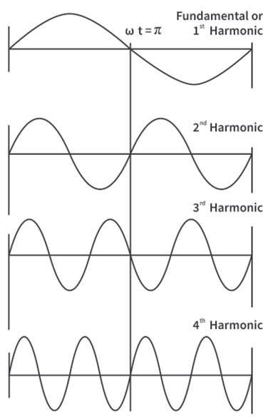
Figure 1: Sine wave frequency
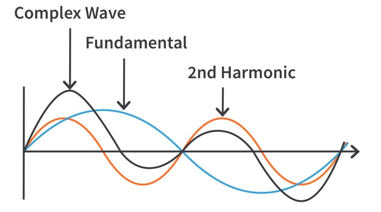
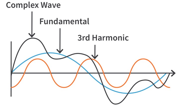
Figures 2 and 3: Harmonic illustrations
What is causing the harmonics in electrical systems?[1]
All electrical loads are divided into two categories, one is linear loads which draw voltage and current in sinusoidal shape, but they may have a phase shift. The resistors, inductors, capacitors, and their combinations fall under this category. The other category is that of non-linear load which draws current in abrupt pulses rather than in a smooth sinusoid, indicating a distorted response. Modern power electronics consisting of inverting, rectifying, charging, and discharging circuits, etc. fall under this category. It is these non-linear loads that give rise to harmonics.
Some sources of harmonics that we see in our day to day lives are CFL/Fluorescent lights, electronic ballasts, fan regulators, UPS and invertors, ARC welders, transformers under no/light load and solar power systems.
Total harmonic distortion is the contribution of all the harmonic frequency currents to the fundamental. [1]
In transmission lines, the stray capacitance which are usually small at standard frequency increases drastically due to the higher frequency harmonics, this leads to poor power quality due to lower power factor.
Why are harmonics bad for the electrical network? [2,3]
Voltage distortions are detrimental to the electrical network, and it can result in the increase of the effective peak voltage value and can also change the RMS value of the current and result in increased losses. In transmission lines, the stray capacitance which are usually small at standard frequency increases drastically due to the higher frequency harmonics, this leads to poor power quality due to lower power factor.
Conductor overheating - A function of the square rms current per unit volume of the conductor. Harmonic currents on undersized conductors or cables can cause a “skin effect”, which increases with frequency and is like a centrifugal force.
Capacitors - can be affected by heat rise increases due to power loss and reduced life on the capacitors. If a capacitor is tuned to one of the characteristic harmonics such as the 5th or 7th. The overvoltage and resonance can cause electric failure or rupture of the capacitor.
In transformers, the iron losses might vary in general with the square of the frequency. Due to the presence of higher frequency harmonics, the iron losses, copper losses or eddy currents in a transformer are increased due to stray flux losses. This might lead to excessive overheating of the transformer and consequent loss of the asset. It may also lead to resonance between the transformer inductance and capacitance which may lead to unwanted vibrations of the transformer core. The use of the appropriate K-factor rated units is recommended for non-linear loads.
In circuit breakers and fuses it can cause tripping and reduce the life of the connected equipment, damaging or blowing components for no apparent reason. [1,2,3,4]
The same is true for motors and generators. The flow of harmonics in the stator generates stray flux which may result in heating of the rotor, pulsating torques, noise generation which affects the overall lifespan of the equipment. Harmonics might also affect the operation of measuring equipment and relays and can also sometimes interfere with communication networks.
Utility meters - may record measurements incorrectly, resulting in higher billings for consumers.
Drives/Power supplies - can be affected by mis operation due to multiple zero crossings. Harmonics can cause failure of the commutation circuits, found in DC drives and AC drives with silicon-controlled rectifiers (SCR’s)
Computers/Telephones – may experience interference or failures.
Evaluating system Harmonics [3]
Some important concepts and terms associated with a harmonic analysis involve PCC, TDD and THD. The Point of Common Coupling (PCC) is the location of the harmonic voltage and current distortion to be calculated or measured. PCC can be measured or calculated on the primary or secondary of a utility transformer or at the service entrance of the facility. In some cases, PCC can be measured or calculated between the non-linear loads and other loads of an industrial plant. Total Demand Distortion (TDD) is the percentage of total harmonic current distortion calculated or measured at PCC. Total Harmonic Distortion (THD) is the total harmonic voltage distortion calculated or measured at PCC.
A task force will be created to develop an application guide for IEEE 519 to help users and utilities in cooperate and understand how to solve potential problems related to power system harmonics.
It is important to evaluate the system harmonics if the facility conditions meet one or more of the criteria below, this is in order to prevent or correct harmonic problems that could occur.
-
The application of capacitor banks in systems where 20% or more of the load includes other harmonics generating equipment.
-
The facility has a history of harmonic related problems, including excessive capacitor fuse operation.
-
During the design stage of a facility composed of capacitor banks and harmonic generating equipment.
-
In facilities where restrictive power company requirements limit the harmonic injection back into their system to very small magnitudes.
-
Plant expansions that add significant harmonic generating equipment operating in conjunction with capacitor banks.
-
When coordinating and planning to add an emergency standby generator as an alternative power source in an industrial facility.

Reducing Harmonics [3]
Harmonics can be reduced in various ways, ranging from variable frequency drive designs to the addition of auxiliary equipment. The following are some of the primary methods used to reduce harmonics.
-
Power system design – Harmonics can be effectively reduced by limiting the non-linear load to 30% of the maximum transformer capacity. If power factor correction capacitors are installed, resonating conditions can occur that could potentially limit the percentage of non-linear loads to 15% of the transformer’s capacity. The following equation can be used to determine if a resonant condition on the distribution could occur.
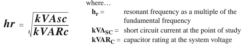
If hr equals or is closed to a characteristic harmonic, such as the 5th or 7th, there is a possibility that a resonant condition could occur.
12 pulse converter front end:
In this type of configuration, the front end of the bridge rectifier circuit uses twelve diodes instead of six. The advantages are the elimination of the 5th and the 7th harmonics to a higher order where the 11th and the 13th become the predominate harmonics. Lower order harmonics have more detrimental effects than higher order harmonics. This will minimize the magnitude of the harmonics but will not eliminate them. The disadvantages are cost and construction, which also requires either a Delta-Delta or Delta-Wye transformer, “Zig-Zag” transformer or and autotransformer to accomplish the 30 ° phase shifting necessary for proper operation. This configuration also affects the overall drive system efficiency rating because of the voltage drop associated with the transformer configuration requirement. Figure 4 illustrates the typical elementary diagram for a 12-pulse converter front end.
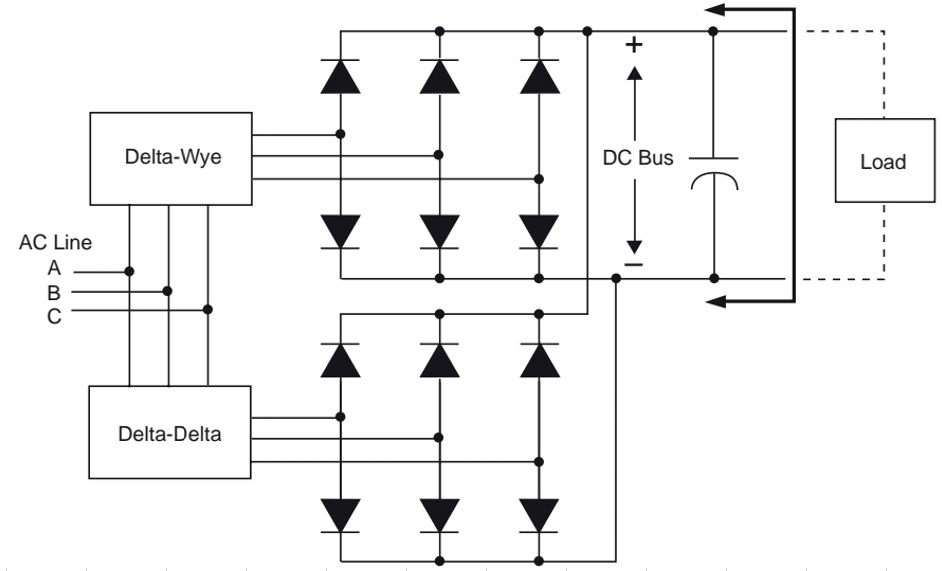
Figure 4: Typical twelve-pulse front end converter for AC drive [3]
-
Delta-Delta and Delta-Wye Transformers: This uses two separate utility feed transformers with equal non-linear loads. This shifts the phase relationship to various six-pulse converters through cancellation techniques, like the twelve-pulse configuration.
-
Isolation Transformer - An isolation transformer provides a good solution in many cases. The advantage is the potential to “voltage match” by stepping up or stepping down the system voltage, and by providing neutral ground reference for nuisance ground faults. This is the best solution when utilizing AC or DC drives that use SCRs as bridge rectifiers.
-
Line reactors – This is more commonly used for size and cost; the line reactor is the best solution for harmonic reduction when compared to an insolation transformer. AC drives that use diode bridge rectifier front ends are best suited for line reactors. Line reactors, commonly referred to as inductors, are available in standard impedance ranges from 1.5%, 3%,5% and 7.5%, respectively.
-
Harmonic trap filters – Used in applications with a high non-linear ratio to system to eliminate harmonic currents. Filters are tuned to a specific harmonic such as the 5th, 7th,11th In addition, harmonic trap filters provide true distortion power factor correction. Filters can be designed for several non-linear loads or for an individual load, as shown in Fig 5 [3]
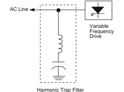
Figure 5: Typical harmonic trap filter configuration
Industrial facilities should include a system evaluation, including a harmonic distortion analysis, while planning facility construction or expansion.
Conclusion
With the proliferation of non-linear loads, the issues of power harmonics are more apparent than ever. Controlling and monitoring industrial system designs and their effects on the utility distribution system are a potential problem for the industrial customer, who is responsible for complying with the IEEE 519, recommended practices, and procedures.
Industrial facilities should include a system evaluation, including a harmonic distortion analysis, while planning facility construction or expansion. Vendors of non-linear loads, such as variable frequency drives, can provide the relevant services and recommend equipment that will reduce the harmonics to comply with the revised IEEE 519 guideline.
References:
1. “Power quality harmonics analysis and real measurements data” by Gregorio Romero Rey and Luisa Martinez Muneta. Intech web
2. “On the impact of Grid Harmonics on Transformers: A case study.” B Thango, O Akumu, LS Sikhosana, A.F. Nnachi.
3. Square D – “Power system Harmonics – Causes and effects of Variable Frequency Drives, Relative to the IEEE 519-1992 Standard”. Bulletin no: 8803PD9402, August 1994, Raleigh, NC, USA