INSULATION CONDITION ASSESSMENT
What methods are available to improve the quality of assessment of line-frequency power/dissipation factor (LF PF) without affecting the productivity and efficiency of maintenance and field staff? Can this new method be easily adapted within routine testing practices? This article aims to answer these questions.
Introduction
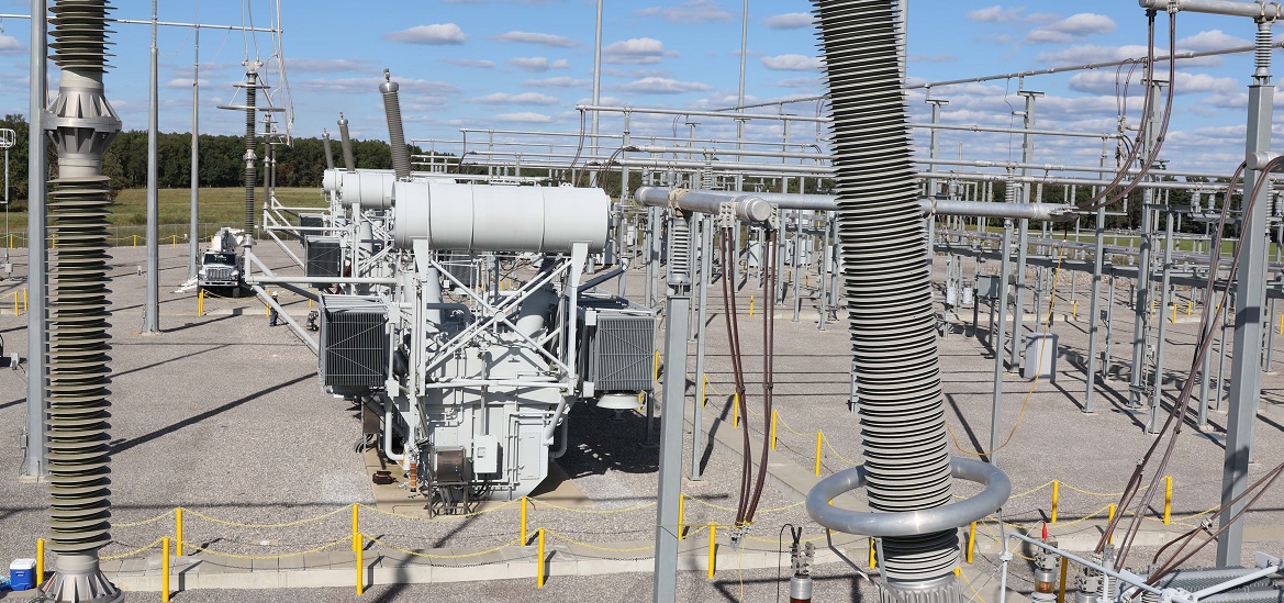
Line-frequency (50/60 Hz) insulation dissipation factor (DF) or power factor (PF) is commonly used in the field for general insulation condition assessment of substation equipment. This common approach to measure dielectric losses in the insulation and quantify as a percentage PF or DF has been performed using portable field equipment with a voltage source up to 12 kV. Measurement of dielectric losses depends on dielectric properties of the insulation material, insulation temperature, geometrical design, as well as aging and contamination that might be present within the insulating medium. Most important to consider is that the insulation system is not perfect, and some losses will be identified.
General limits have been established for line-frequency (LF) PF/DF measured in liquid-impregnated power and distribution transformers and guidelines have been given to field users. It is important to mention that PF/DF test equipment does not only measure %PF but also provides a measurement of capacitance, watt losses, and resultant current. All of them are important for overall condition assessment.
Nevertheless, field users from different parts of the world have encountered situations where a transformer or bushing with a recently tested good %PF value failed in the field shortly thereafter.
Then the question for most asset managers is: What methods are available to improve the quality of assessment of line-frequency power/dissipation factor (LF PF) without affecting the productivity and efficiency of maintenance and field staff? Can this new method be easily adapted within routine testing practices?
Line-Frequency Power Factor (LF PF)
In a liquid-immersed transformer, LF PF is measured winding-to-winding and winding-to-ground, typically at 10 kV (or below rated voltage of the winding under test) and at line-frequency or at frequencies very close to it.
As mentioned above, LF PF is temperature-dependent which leads to an additional requirement in the assessment process – normalization to a base temperature value (20°C).
In the last 25+ years, the electrical power industry has seen added value provided by the analysis of dielectric losses at frequencies different from 50 or 60 Hz (Dielectric Frequency Response).
Is DFR a viable path to help clarify doubts related to LF PF measurements? What are lessons learned and how can this tool be used to support routine testing in the field?
Looking into the alternatives and the physical capabilities of the PF/DF test set, the ability to measure dielectric losses in a spectrum of frequencies from 1 Hz and up to 500 Hz was implemented.
Line-frequency insulation dissipation factor or power factor (LF PF) is commonly used in the field for general insulation condition assessment of substation equipment.
Measurement in this spectrum of frequencies does not imply significant addition of testing time but opens the opportunity to also measure PF/DF at any other frequency in this range as part of the routine LF PF test.
Now that the test set can measure dielectric losses within this frequency spectrum, the traditional LF PF test takes a major step further towards improvement and ease for condition assessment. LF PF/DF is not any more a one-point/single reference that may or may not be influenced by degradation or contamination in the complex insulation system under test. Between 10 and 100 Hz, the dielectric response is typically very linear (especially at temperatures between 0 and 25 °C) whereas the range between 1 and 10 Hz is at least 10 times more sensitive to insulation degradation. For dielectric analysis, the amount of information in each logarithmic decade (1 Hz to 10 Hz; or 10 Hz – 100 Hz) is of similar importance.
Therefore, the use of an additional frequency value while performing the LF PF/DF test is a practical approach to leverage technical assessment on two points within the dielectric spectrum of the insulation under test.
Power Factor at 1 Hz
For liquid-immersed systems tested at or close to 20°C, the frequency range between 10 and 500 Hz displays a very linear characteristic when losses are low. Measuring PF at lower frequencies, the dielectric response encounters a frequency range represented by high losses and greater dispersion. The point of transition is called resonant frequency and it will shift depending on temperature (see Figure 1), insulation materials, and level of contamination or degradation of the insulation.
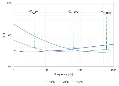
Figure 1. Resonant frequency shift in a dielectric response at different temperatures
The use of an additional frequency value while performing the LF PF/DF test is a practical approach to leverage technical assessment on two points within the dielectric spectrum of the insulation under test.
The variation of LF PF as a function of temperature is very small as compared to that observed at 1 Hz, especially for a healthy and dry specimen (<0.5% moisture in the solid insulation) immersed in good liquid insulation (conductivity <0.37 pS/m). When the condition of the insulation changes, the thermal response of LF PF also changes, and these changes may be overseen when temperature correction is not performed properly.
The research work carried out in liquid-immersed transformers and bushings using wide spectrum dielectric frequency response testing techniques is extensive. From this research, recommendations were made for 1 Hz PF limits for OIP transformers (Table 1) and OIP HV bushings (Table 2).
Field Experience
Routine testing on a service-aged transformer
A 1978, 20 MVA, 69/13.09 kV, Dyn1 transformer was taken out of service to repair a pump in the cooling system. The technical maintenance team completed the required repairs and conducted a complete protocol of routine commissioning tests including a regulatory 10 kV line-frequency (LF) power factor (PF) test.
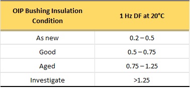
Table 1. OIP bushings assessment for 1 Hz DF at 20°C
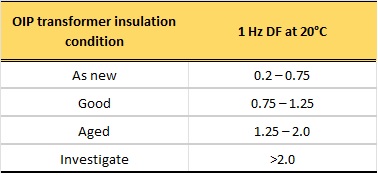
Table 2. OIP Transformers assessment for 1 Hz DF at 20°C
The overall capacitance and line-frequency power factor (LF PF) test at 10 kV is carried out using Megger’s DELTA4000 power factor (dissipation factor) test set at a top-oil temperature (TOT) of 30°C.
The overall line-frequency PF results are normalized to 20°C using the individual temperature correction (ITC) algorithm showing a “Good” overall condition of the insulation (Figure 2). Without any additional information, it would be assumed that no additional work needs to be performed on the transformer to improve its lifespan.
As part of the routine test, 1 Hz PF was measured and corrected at the same time LF PF was carried out. The 1 Hz PF values obtained are much greater than those considered in Table 2 for service-aged transformers and the system calls for Investigation [I] as presented in Table 3.
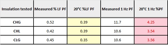 Table 3. Overall LF and 1Hz PF results for 1978 Tx
Capacitance C1 of the HV bushings are tested at an estimated bushing temperature of 22.5°C (as an average between ambient and top-oil temperatures).
Line-frequency power factor (LF PF) on all HV bushings shows values doubling or nearly tripling the nameplate reference values (see Table 4). These elevated values warrant investigation.
Again, ITC is used to normalize LF and 1 Hz PF results to 20°C in Table 4.
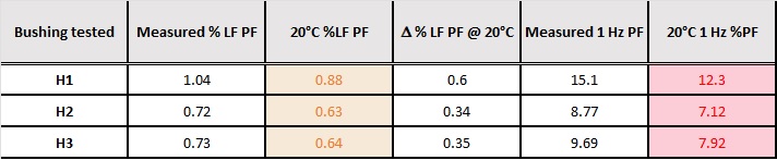
Table 4. HV Bushings C1 capacitance LF and 1 Hz PF results
Results in Table 4 lead to a decision to replace the HV bushings. The transformer oil was drained and the HV bushings were removed from the unit. Figure 2 shows a layer of contamination on the bottom section of the bushings.
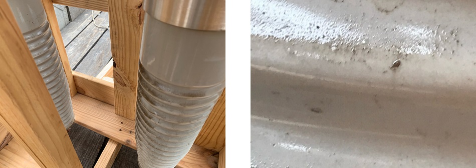 Figure 2. HV bushing removed from the transformer – surface contamination
Based on these findings, the owner decided to filter the oil to ensure the removal of all particulates.
New bushings were installed on the HV side of the transformer, and they tested at an estimated bushing temperature of 24.5°C. Excellent LF and 1 Hz PF values were obtained on the C1 capacitance as presented in Table 5.
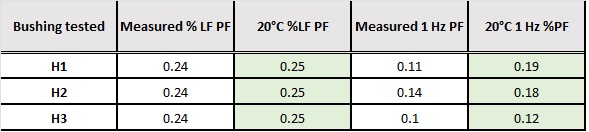
Table 5. HV Bushings (new replacements) C1 capacitance LF and 1 Hz PF results
With the HV bushings replaced, the oil filtered, and under the same test conditions, the overall LF PF test was carried out and results show clear improvement, as presented in Table 6.
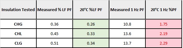
Table 6. Overall LF PF results after oil process and HV bushings replacement
As with LF PF values, 1 Hz PF did improve but assessment indicates that the unit requires further investigation. Why would the 1 Hz PF values still be high after HV bushings replacement and oil filtering?
To answer this question, and based on the 1 Hz PF results, the owner of the equipment requested a definitive analysis of the insulation system using Megger’s Insulation Diagnostics Analyzer IDAX300S to obtain a wide spectrum (1 mHz – 1 kHz) dielectric frequency response (DFR) and determine the condition of the entire insulation system inside the transformer.
Full-spectrum DFR shows that the interwinding solid insulation contains a typical % moisture (1.7%) for a service-aged transformer but the liquid insulation reports high conductivity (11.8 pS/m).
Further internal inspection of the unit shows that tank walls and paper insulation retained contamination material in areas difficult to be removed. It was recommended now to flush the core-coil assembly several times to remove contamination. Samples were taken and sent to the laboratory for analysis.
It is important to mention that historical DGA data did not alarm the operator. In Duval Triangle 1, values fluctuated within the T1 region.
Conclusions and Recommendations
Line frequency PF (DF or tangent delta) measurements by themselves may or may not reflect the true condition of the insulation system inside a transformer.
-
It is a fundamental practice to record a benchmark signature of the dielectric condition of a power transformer before any maintenance work is carried out.
-
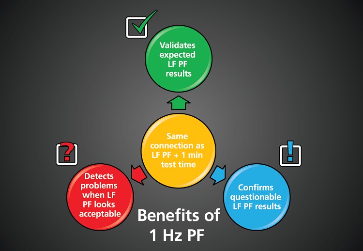
Identify deviations from practical references besides LF. 1 Hz complements, confirms, and verifies the information obtained by LF PF.

Figure 3. Dielectric Response after oil-processing
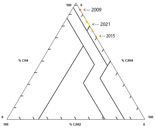
Figure 4. DGA trending - analysis in Duval triangle 1
The use of LF DF together with 1 Hz DF results properly corrected to 20°C using the Individual Temperature Correction (ITC) algorithm provides higher sensitivity to changes in the insulation system of HV equipment.
1 Hz measurement is a valuable addition to the “ROUTINE” testing procedure for insulation condition assessment of liquid-impregnated transformers and bushings.
The combined analysis of LF DF + 1 Hz DF (ITC corrected) allows for numerical condition assessment of new and service-aged transformers and bushings as suggested by the authors in Tables 1 and 2. The 1 Hz DF with ITC assessment does not require trending analysis, although it is also possible to trend this value. Moreover, average factors used for temperature correction which are obtained from generic tables do not represent the immediate dielectric condition and thermal behavior of PF. End-users should consider the implementation of the ITC algorithm for reliable assessment of results and proper trending over time.
The traditional 10 kV LF DF together with the 1 Hz DF (ITC corrected) marginally increases the testing time (< 1 min). The testing approach presented in this paper helps extend the life of HV and EHV assets providing sufficient support for future sound technical and financial decisions or future investigation and definitive analysis using DFR technology.
1 Hz measurement is a valuable addition to the “ROUTINE” testing procedure for insulation condition assessment of liquid-impregnated transformers and bushings.
References
-
CIGRE TB 755, Transformer bushing reliability, CIGRE WG A2-43, 2019
-
Güner, D.M. Robalino. P. Werelius, “HV and EHV bushing condition assessment – field experience,” Proceedings of the 2016 CIGRE-IEC Colloquium, Montreal, Canada, 2016
-
Robalino, R. Alvarez, “Advances of Dielectric Frequency Response Testing for HV OIP Bushings,” Proceedings of the CIGRE Session 48, paper A2-206, Paris 2020
-
M. Robalino, R.C. Breazeal, “Evaluation of Distribution Class Transformers Using Narrowband Dielectric Frequency Response Measurements,“ Proceedings of the IEEE 2020 Electrical Insulation Conference, 2020

Diego Robalino
Diego Robalino is the Business Development Director – Power Transformers at Megger. Diego is a Senior Member of IEEE, a member of IEEE/PES Transformers Committee, a certified Project Management Professional with the Project Management Institute (PMI), and the General Chairman for the IEEE/DEIS 2022 40th Electrical Insulation Conference. He is the author and co-author of over 40 technical articles related to power, distribution, and instrument transformer condition assessment. Diego received his Ph.D. in Electrical Engineering from Tennessee Technological University.

Vince Oppedisano
Vince Oppedisano is the Transformer Product Specialist at Megger in the Valley Forge, PA factory. Vince has dedicated more than 35 years to the electrical testing industry. He has represented Megger at several technical and commercial events worldwide. He is a dedicated product development leader devoted to power and instrument transformer testing and diagnostics.