AND THE SERIES CONTINUES
Foreword from the Editor in Chief
One of the most enjoyable aspects of reading Chuck Baker’s continuing saga of the implementation of best practices for testing, maintenance and monitoring of a high voltage system, with particular emphasis on transformer reliability, is to be able to follow the characters. His grasp of the personas that we deal with in the industrial world is what makes this story unique. I certainly hope you enjoy Chuck’s wonderful perspective as much as I do.
CAST:
Brian ………………… Regional Vice President (head person for Smith Industries plant)
Andy…………………. Reliability Manager of Electrical Power System (recently hired by Brian)
Kevin…………………. Director of Reliability
Jill…………………….. Director of Operations
Tina…………………… Maintenance Manager (reports to Brian also)
Tim …………………… Electrical Engineer (reports to Andy)
In the last article, Brian (Regional VP) let us know that Andy (Reliability Manager) would begin to integrate The Reliability Plan of the power system into the plans for the Arc Flash Study. Take it away Andy.
Hello to everybody. A quick update: I have talked with the key players involved in the reliability movement within Smith Industries. As you recall, under the direction and expertise of Brian, most of the plant is in the process of building reliability programs. The area that lags is the power system and that is why Brian brought me on board.
I explained about the upcoming scheduled outage and the need to perform an arc flash study as the last one completed was over five years ago, and we are required by code to do it – now. I introduced the need to start to walk through the reliability program for the power system at the same time. Brian, Kevin (Director of Reliability) and Jill (Director of Operations) have given us the thumbs up, and so now it’s time to take the first step – and that will be tomorrow morning with the core team: Tim (my EE) and Tina (Maintenance Manager). The three of us must be unified, maintain a clear understanding, and everything else Brian explained to us in last month’s article.
Tim and I have a small conference room between our two offices, and it was perfect for our all-day meeting. I brought the coffee and doughnuts and figured we would need a break and going out to lunch would work.
I set up a small projector, hooked my surface up to it, brought up my very short, three-slide Power Point. Within a couple of minutes I was ready, and both Tim and Tina had arrived and were settling in.
I started the morning with a quick overview:
- Good morning all. Excited that we can get started on looking at what we want and need for a power system Reliability Centered Maintenance (RCM) program.

Tina, I know you have been working on this for other portions of the plant, and Tim, I know your background centers on power system maintenance, so let me take a couple of minutes and communicate the way I think about this.
Tina interrupted and asked about how long the meeting is. She said a strange thing happened when she accepted the meeting; it filled both today and tomorrow on her Outlook. I explained that I was not sure and wanted to make sure nothing conflicted with all of us getting on the same page. Any other questions?
Both had a cup of coffee, sat back, and said: “Let’s do it!”.
- First, let me tell you my definition of an RCM program. Brian and I agree, and I think you will too:
An RCM approach is a corporate driven program to optimize the maintenance program so that the productivity of the plant is maintained using highly effective, priority and risk based, cost-effective techniques. When done correctly, the program will allow you to control what we have assumed was uncontrollable in the past.
Tina, let me walk you through my program strategy and we can see if it is compatible with your plant RCM program. We cannot have any conflicts between the two.
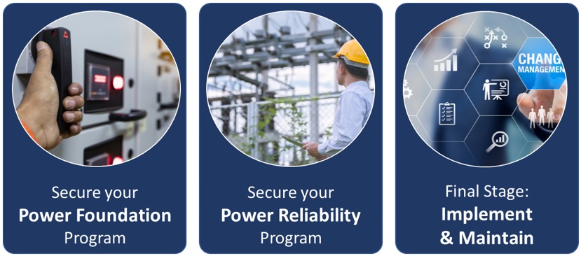
I break it down into three key stages: Foundation, Reliability, and Implementation.
When we talk about our plants power system, we are talking about 25 individual components. The sum of these are the power system. Each component has its own key factors such as age, quality, health, load, or heat, etc. To build the program, we must go out into the plant, go through the engineered drawings, and utilize the information gathered during our arc flash investigation to collect all data required for a program.
The first step, Secure you Power Foundation Program, has 8 key stages that we will use to secure the program foundation:
-
One-Line Diagram
-
Short Circuit Study
-
Coordination Study
-
Arc Flash Study
-
Maintenance Standards
-
Service History – Current Status
-
Required Actions
-
Implementation
When we get through these 8, we will have a strong foundation to begin to build the reliability side of the program. As with any new program, we need to stay on the same page.
With that said, and before we start walking through each of the eight, we need to talk about the CMMS system the plant is currently using. I was not familiar with your program, but have looked at it, and see it is a good one for plant maintenance. I have used a different program that is specially designed for the power system and is set up with standards, work plans and methods to rate the value and reliability assignment for each piece. This would work in conjunction with your current one. The reason I mention this is that the exercise of the first 8 will generate critical information for our reliability program, and we want to have the right place and program to collect and organize what we generate.
Once we get through these 8, and have all data collected and entered, we will take the fun step – the reliability step. When we get there, we will have our 8 Reliability Steps to complete the program.
OK, let’s walk through each of the eight steps and make sure we are on the same page.
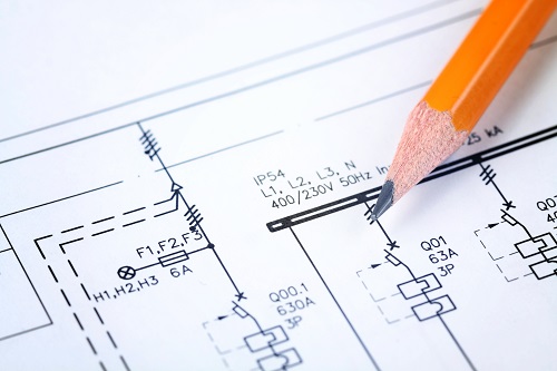
One Line Diagram
This is a diagram that takes your three-phase power system and with single lines, component symbols show all arrangement of all components including key data (voltage, resistance, etc.), main connections, switching, etc. This is a key document in the management and servicing of your power system. More importantly, this is a critical document for maintenance of the system. A critical safety component is to verify switching, lock out etc. This is for our electricians, and just as importantly, our contractors who are servicing our system. They need to see the circuit and switching flow to assure the equipment is down before they ground it for service. Obviously, there will be continual changes that will require for the one line to be updated.
Tina jumped in and reminded me that they do in fact have a good one line, and then Tim jumped in before I could say anything and explained to her that although they do have one, it is out of date. Regulations and codes require the one line to be reviewed and updated every five years or when a significant change is made.
I was pleased that Tim was onboard and was becoming a spokesman for the reliability program. He went on to explain that we would contract a PE to come in and perform this and that Tim would walk the system and provide necessary documentation and back up data for the PE.
I agreed with Tim and thanked him for updating us on those key points. I continued by saying that this is where it gets interesting.
- Think about this. We will review every component, its rating, etc., and will put all of that data into our power reliability CMMS. In a couple of minutes we are going to walk through the Short Circuit Study, Coordination Study and Arc Flash Study, which is also a requirement for program review every five years. And gang, these three all require the data that will be gathered in the one line, a perfect package.
So, you can see why the updating of this document is important. Let us go over the other three that we will be doing to build our Power Foundation Program.
Short Circuit Study – Coordination Study – Arc Flash Study
The reason I want to walk through these three simultaneously is because they will all work hand in hand and be performed as a part of this requirement.
A quick summary:
-
The Short Circuit Study will look at protective devices and calculate the line to ground fault currents that could be generated. This tells us about the available power and looks at the protective device duty rating that is responsible to clear the fault. When the PE performs this, we will use the updated one line diagram and use the information for these calculations from that.
-
The Coordination Study takes the available fault current and looks at the nearest protective device upstream. It calculates if that device will do its job, isolating the fault and not allowing the impact to harm the feeder upstream. The PE will look at the time vs. current characteristics of each device and compare it to the protective devices upstream.
-
The Arc Flash Study is critical, not just because it is a regulated requirement, but because it provides safety for those who are working on or around our Power System.

-
The first step in performing the arc flash is to gather all data on the equipment and system. It will start with the utility company’s available short-circuit current and protective devices. We will then gather all data from components such as conductors and transformers and other sources of short circuit power. You can see how all the work done on updating the one line is important for all of this.
-
The PE will then take all that data and calculate the potential “arcing” short-circuit current. The arcing current results when the short-circuit current jumps across an air gap. Again, remember we gathered a lot of relevant data when completed the short circuit analysis.
-
The next calculation is to determine the Arc Flash Duration. This takes the amount of short circuit energy available and calculates how long it will take the protective device to open and end the short circuit.
-
We will calculate the incident energy which tells us what the safe working distance is. If this switch were to arc, the person would need to be 18 inches, or 24 inches, or 36 inches, etc. from the source.
Tina jumped in and pointed out that the time, temperature, and damage all the way up to fatality was talked about in our first meeting with Brian and the gang. Tim jumped in and pointed out that this is regulated and required, but for all the right reasons pointing out the number of deaths and serious burns that happen every year from arc flash incidents.
I was encouraged that they were engaged and following the outline logic. I continue:
-
Now that we know the energy and time that would be present in the event of an arc flash, we will calculate the arc flash boundaries. This begins to narrow down as each location will be labeled for safe working distance.
-
A part of the calculation for distance also calculates the level of Personal Protective Equipment (PPE) that is required at that location. Length and strength of the potential arc helps determine the required PPE.
-
The PE performing the study places arc flash warning labels where required. This label is what communicates the requirement for distance and PPE to the person performing the work.
-
The last step is training the crews and those who could be exposed to an arc flash. I mentioned that the arc flash study was due every five years. The other part of the program is the crew training which needs to be performed every three years. I know that the power group does annual OSHA safety training and I am certified to provide this arc flash training. We will schedule that with this annual training every third year.
Tim did a great summary of the first four steps to a Power Foundation Program, saying that these four key requirements work in conjunction with each other. All the data is shared, key calculations are performed, and the results will work for each of these, allowing us to pull this into compliance. He also reminded Tina and I, I think mostly me, that not only would we be gathering key data, but we would also find settings and equipment that needed to be adjusted or replaced as we did each of these. He also pointed out that all the base data we needed for our reliability program would be gathered during this phase.
I agreed and proposed we run out for some lunch and a little fresh air; they were great with that.
I believe this is the end of this month’s article. This afternoon, or I should say the next edition, will be our team walking through the last four items:
-
Maintenance Standards
-
Service History – Current Status
-
Required Actions
-
Implementation
These sound simple, but they are not. These are tough, but necessary steps for the foundation of the reliability program.