IMPORTANCE OF THE COOLING SYSTEM
Foreword from the Editor in Chief
Did you ever battle with a transformer that had a dangerously high operating temperature? Transformer operating temperatures are an extremely important parameter for the industry. This will determine to a great extent the actual time the unit can be used in the reticulation system before replacement. In this article, Kevin and his team came up with some very practical real-life applications to decrease the operating temperatures, giving the transformers a new lease on life. The case studies will add enormous value to the knowledge vault of any utility.
Aging Grid
According to the U.S. DOE analysis of the U.S. Power Grid, the average age of power lines and transformers in the North American grid is over 28 years, while power generation plants are decades old [1]. Science News says that “The U.S. power grid in many cases is a 19th century system design operating under the stresses of a 21st century load and climate” [2]. The American Society of Civil Engineers (ASCE) said in its 2017 Infrastructure Report Card, which rated energy infrastructure at a D+, that “most electric transmission and distribution equipment were constructed in the 1950s and 1960s with a 50-year life expectancy” [3]. With transformers being a vital component of any electrical grid and maintaining these assets being of the upmost importance, we have to ask ourselves, how well are we managing the critical components of these transformers?
With transformers being a vital component of any electrical grid and maintaining these assets being of the upmost importance, we have to ask ourselves, how well are we managing the critical components of these transformers?
Importance of the Transformer Cooling Systems
First, let’s talk about cars and trucks. Most people perform routine maintenance on their automobile such as changing oil, air filters and giving it a wash and a rinse every once in a while. What about your radiator and the cooling system? Most people do not know they have an issue with their cooling system until some type of an indicator alerts them that something is wrong, or they are left stranded on the side of the road with an overheated engine. The same or a similar type of cooling system technology is installed on most power transformers. In too many cases, they receive about the same amount of attention as the car that was left stranded from an overheated engine.
Now, let us talk about why we cool transformers to begin with. Elevated temperatures accelerate aging of insulation paper. The life of a transformer is measured using the degree of polymerization (DP) of the insulating paper and aging, or the remaining life of a transformer is measured as the inverse of DP. Temperature affects lifetime, and this is given by the Arrhenius equation that shows that the life of a transformer is approximately reduced by 50% with every 8°C rise in temperature.
High temperature also accelerates aging of insulating paper in the presence of moisture. The cooling system is one of the most important parts in the normal daily operation of a transformer, and, if it does not operate properly, it will reduce the life of the transformer. Without the cooling system operating properly, loading is limited (due to the fear of loss by overheating, causing irreversible damage to the insulation system paper and oil) and in the worst case, this may lead to the loss of the transformer. In cases of high loading over extended periods, it may become the most critical component for keeping the transformer operating. Even with periodic and routine maintenance schedules most cooling systems will develop problems before the end of the transformer’s life.
Reasons for Cooling System Failures
Corrosion is the largest contributor of cooling system failures. Whether it is caused by outside atmospheric or internal anomalies such as high moisture levels, the corrosion process degrades the cooling system at an accelerated rate, compared to the transformer itself. Various forms of corrosion attack cooling systems, such as electrochemical and anaerobic corrosion.
According to the U.S. DOE analysis of the U.S. Power Grid, the average age of power lines and transformers in the North American grid is over 28 years, while power generation plants are decades old.
It is a known fact that saltwater accelerates corrosion at five times the rate of freshwater. Humid salt air corrodes at ten times the rate of average air at average humidity. Various other chemicals such as sulfides, chlorine and alkaline solutions will also accelerate corrosion. In today’s grid, transformers are being moved frequently from one site to another. Some transformer cooling systems that were originally designed for inland operation and have been moved to a coastal or industrial environment will begin to corrode at accelerated rates. In some cases, end users are misinformed about the ability of hot dip galvanized radiators and cooling products to resist corrosion in many environments, especially when fans are used directly in the cooling process. In many cases the corrosion rate is accelerated beyond the galvanic action of “self-healing”, therefore allowing corrosion to attack the base substrate of the cooling system materials. The next largest contributor to cooling system failure or underperformance is high heat loads. These loads can be caused by steady temperature rise due to paper depolymerization, or intentionally increased loads on the transformers. Other factors, such as the increase of transformer harmonic with age, UV breakdown of coatings, and blocked or fouled heat exchange surfaces can also affect the efficiency of the cooling system.
Solutions and Options
Cooling system replacements or upgrades are generally transformer specific. In either case, it is essential to understand what the current system is designed to cool and what the desired result needs to be for the end user with a new system. Many factors have to be taken into consideration when designing a new system, such as space requirements, current transformer performance, materials and coating requirements, desired cooling vs. load expectations, type of transformer fluid used, as well as other details. Often, simply replacing the original equipment may not give the desired outcome needed. This is especially important when dealing with legacy transformers that have been relocated, or are operating at higher loads than historically seen since being placed in service. At times there are easy solutions for upgrading or adding capacity to transformers.
Even with periodic and routine maintenance schedules most cooling systems will develop problems before the end of the transformer’s life.
Adding fans to an ONAN cooled system will increase cooling capacity while giving the asset owner an ONAN/ONAF cooling system transformer. Understanding the relationship between the heat exchanger design and performance, fan performance, fluid dynamics as well as other inputs such as ambient air and mass flow, are critical. On other occasions, upgrades may be more complicated, for example with directed flow transformers or when pumps are part of the cooling system.
|
|
Corrosion is the largest contributor to cooling system failures; and often, simply replacing the original equipment may not give the desired outcome needed.
Case Studies
Example 1
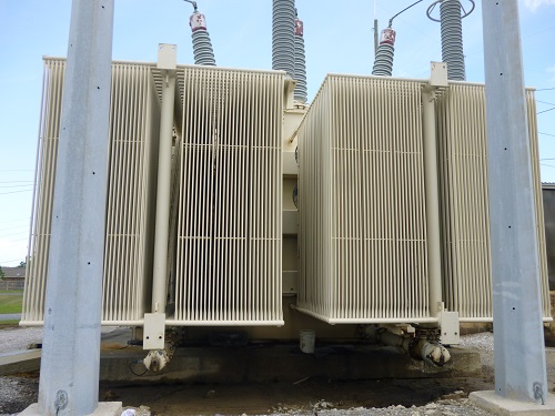
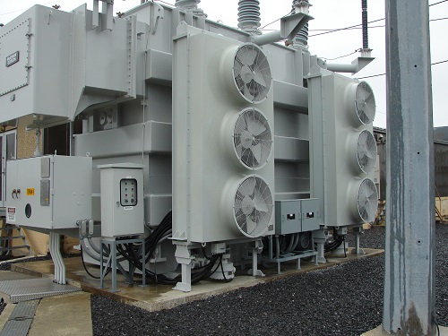
In this case, an ONAN transformer was experiencing higher loading than previously seen. This was one of the eight transformers located at various substations within the Kentucky Utilities (KU) network. In an effort to improve cooling capacities for extending life on these network transformers, KU decided to add fan cooling systems to each transformer. The scope was to model and design a fan cooling system including fan control cabinets that would connect to new temperature gauges. The system was modeled along with custom fabricated fan mounts and then installed. Cooling capacity was increased by an estimated 30%+ while making this an ONAN/ONAF method of cooling.
Transformer was retrofitted with a new ONAF cooling system including a fan control box and custom fan holder apparatuses, see Figure 1.
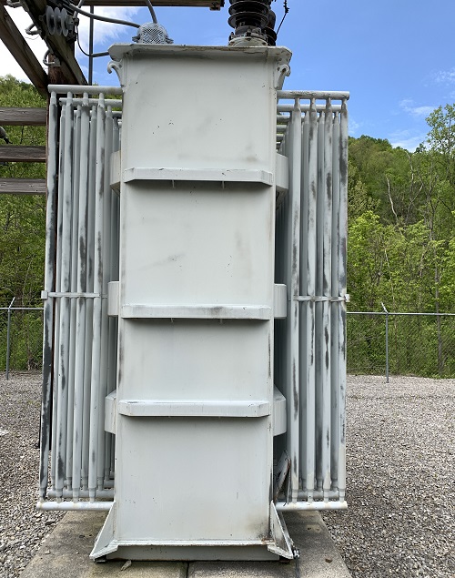
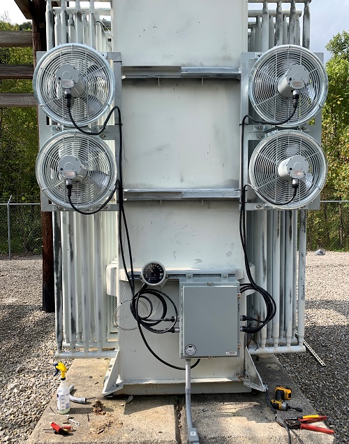
Figure 1. Cooling system upgrade on an LG&E and KU transformer: Before (left) and after (right)
Example 2
This is a case where manifold cooling systems using tubular radiators have reached their end of useful life. The transformer cooling system had developed leaks in the piping, pumps and tube assemblies. A new cooling package was developed, complete with a redesigned manifold system. After installation of the new cooling package, the customer observed an average of 9°C cooler operating temperatures. This system was installed as part of a complete life extension project for this Westinghouse 100 MVA transformer.
The project was repeated for the sister transformer within the same station, see Figure 2.
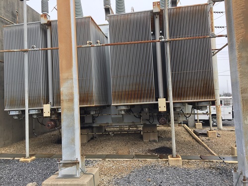
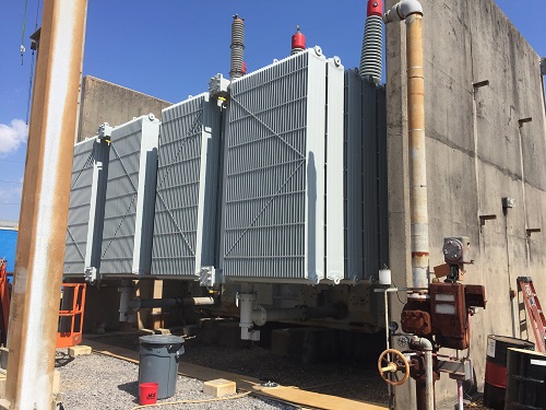
Figure 2. Replacement cooling systems on a Westinghouse 100 MVA transformer: Before (left) and after (right)
Example 3
In this case, a cooler was replaced with a bank of radiators at a copper mine. Due to the severe dusty environment, the coolers were frequently getting clogged, making the maintenance of the cooling system a nightmare. Again, with the help of the heat run test report, the appropriate size of a replacement radiator cooling system was designed, see Figure 3.
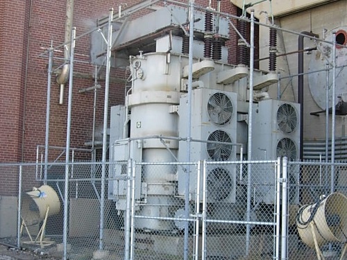
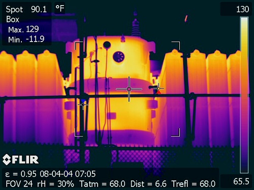
Figure 3. Replacement cooling system for the mining project: Before (left) and after (right). Thermal scans after the installation of the new radiator package show improved cooling and operation.
At this site, the oil temperature was monitored with high temperature alarms. Prior to installation of the radiator cooling system the high temperature alarm system would trigger frequently but after the replacement there have been no such alarms. Note that the additional blowers were abandoned after the replacement.
Example 4
Here is another example of a cooling system type change. The key factors in the installation of a replacement cooling system were to:
-
Increase cooling capacities to enhance the planned transformer life extension project by 15%
-
Design a redundant system to assist in maintenance and provide critical fail-safe coverage
-
Design a system in which the center of mass is closer to primary supports to help remediate subsidence.
Basically, the transformer and substation were sinking slightly year over year.
The cooling system was converted from an ON/ONAF/OFAF type to a primary OFAF type with redundancy. The center of mass was improved by 65% allowing the customer to have a system supported by the primary transformer pad rather than the transformer radiators in a cantilevered fashion. The weight of the system was reduced from nearly 30 tons to 5,3 tons, see Figure 4.
Before: Original manifold assemblies
After: New fail-safe OFAF cooling system
Figure 4. Cooling system type change: Before and after
References
-
The U.S. Department of Energy, “Large Power Transformers and the U.S. Electric Grid,” available at https://www.energy.gov/sites/prod/files/2014/04/f15/LPTStudyUpdate-040914.pdf
-
Maria Temming, “The U.S. power grid desperately needs upgrades to handle climate change,“ Science News, available at https://www.sciencenews.org/article/u-s-power-grid-desperately-needs-upgrades-handle-climate-change
-
American Society of Civil Engineers (ASCE), “2017 Infrastructure Report Card,” available at
https://www.infrastructurereportcard.org/wp-content/uploads/2016/10/2017-Infrastructure-Report-Card.pdf -
Arshad, Islam and Khaliq, “IEEE Power Transformer Aging and Lifespan,” 2004
-
V. Vailoor, “Thermal Performance of the Radiator for Electrical Transformers,” available at
https://www.scribd.com/document/332364908/Test-de-Radiador -
Kido and Kobayashi, T&D World “How Transformers Age”, 2019
-
Lightner, DOE, “Report on Grid Reliability”, 2005
-
C57.93-2019, IEEE Guide for Installation and Maintenance of Liquid-Immersed Power Transformers