VISUAL INSPECTIONS OF COMPONENTS FOR INCREASED RELIABILITY
Perhaps more than ever before, transformer reliability is of vital importance. It has always been crucial to safety and productivity, but having unreliable electric power equipment is a significant risk for those who rely on uninterrupted power for their operations. Recent changes to essential guides—notably NFPA 70E and NFPA 70B—are more direct in how we must consider and comply with safety and maintenance requirements. This article explores the critical visual inspection of the components of a transformer and how the standards of NFPA 70B affect those who manage and maintain transformers, the most valuable asset in most settings.
Having unreliable electric power equipment is a significant risk for those who rely on uninterrupted power for their operations.

Figure 1

Figure 2
Specifically, this article discusses the newly NFPA 70B-directed requirements regarding transformer safety and reliability. The directives include time-based liquid and electrical testing along with regular visual inspections, which include components such as bushings, radiators, tank condition, gauges, and other accessories.
Visual inspections, perhaps easier to perform as they do not require an outage, are now mandated to be supplemented with regular dielectric liquid and electrical testing. The combination of the two—visual inspections and regular testing—goes a long way in providing the comprehensive reliability condition of an asset.
Visual inspections, perhaps easier to perform as they do not require an outage, are now mandated to be supplemented with regular dielectric liquid and electrical testing. The combination of the two—visual inspections and regular testing—goes a long way in providing the comprehensive reliability condition of an asset.
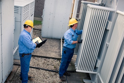
Figure 3
First, we will outline a few key definitions referenced below in the discussion of visual inspections and transformer components.
Key Definitions
Accessories are the components of the transformer other than the dielectric liquid, core/coils, and tank. Generally included are bushings, radiators, gauges, pumps, and fans.
Bushings are the conduit by which the electrical energy can enter and exit the transformer. The bushing is a hollow electrical insulator that facilitates the passage of an energized, current-carrying conductor.
Dielectric Liquid Mineral oil has traditionally been used in most liquid-filled units. Along with mineral oil, natural esters, silicone, and high molecular weight hydrocarbons make up most of the liquid types found in distribution and power transformers.
Dissolved Gas Analysis (DGA) of the dielectric liquid is the standard test method for the analysis of gases dissolved in electrical insulating liquid by gas chromatography (ASTM D3612). Subdivided by what are referred to as combustible gases, the profile gases indicate various conditions in the transformer, from a normal gas situation to one with high energy gases such as acetylene that indicate arcing.
Infrared Detection, using an infrared camera, gives a thermal scan with a digital photo that can determine both temperature and temperature gradients on an object.
NFPA 70B is the document published by the National Fire Protection Agency, often enforced by OSHA, for the standards of electrical equipment maintenance.
NFPA 70E is the document published by the National Fire Protection Agency, often enforced by OSHA, for the safety and procedures of workers regarding electrical equipment and its maintenance.
Partial Discharge (PD) is a small, localized breakdown of solid or liquid insulation. In oil, it is characterized by the creation of hydrogen. It can be detected by ultrasound.
Bushing Inspections & Testing
Beginning with the bushings and lightning arrestors, the electrical testing of the transformer includes testing the components with insulators for their proper function and comparing data to OEM or industry standards such as IEEE and IEC. Transformers and bushings sometimes undergo electrical testing (ET) as often as every year, or now, per NFPA 70B, no less than every five years. Every three years, by many, is considered a reasonable goal. ET is, of course, an intrusive, outage-required procedure. There are also viable, energized diagnostic procedures such as the informative data provided by infrared scanning, bushing monitoring, and, less commonly, ultrasound diagnostics.

Figure 4
A comprehensive program for the status of bushings would include five different approaches, the first four of which can be performed energized.
-
Infrared scanning is an economical procedure and one of the recommended inspections in NFPA 70B Section 9.2. Some of the problems that can be identified include:
-
Loose or poor internal connections
-
Loose or poor external connections
-
Unbalanced loads
-
Bushing failure
-
After an initial outage for the installation, transformers with bushings that have capacitance taps are candidates for Bushing Monitoring. Whether stand-alone or coupled to an online DGA monitor, the data provides peace of mind surveillance, continuously tracking bushing capacitance, power factor, and Partial Discharge (PD) activity.
-
The Visual Inspection of bushings can be done even from a viewing position outside the substation with magnification. The inspection can notice leaks, discoloration, cracked insulators, and the buildup of dirt.
-
Ultrasound Detection: In addition to measuring PD activity within the bushings, bushing monitoring technology allows the user to measure PD activity within the transformer and can tell where the PD is located, whether that be in the bushing or windings, and which phase or phases are affected. The beauty of bushing monitoring is being able to trend these values where alarm setpoints will alert you to potential issues at that time rather than waiting for the next planned maintenance outage. Additionally, corona (when it is at an advanced stage) will produce a heat signature.
-
Finally, the outage-driven Electrical Testing of the Bushings is carried out via the bushing terminal, ground connection, and fitted C2 test taps. Where a C2 test tap is not available, a hot collar test can be performed instead. This testing is guided in NFPA 70B Section 9.2 and varies based on condition from 1 to 5 years. Capacitance taps are usually found on units 69 kV and higher.
Other visible components on the outside of a transformer can be inspected without an outage, similar to bushing-related visual inspections. These inspections align well with dielectric liquid sampling and can often be achieved while the transformer is energized. Inspections called out in NFPA 70B are, for the most part, required annually, but vary by the condition of the equipment. These inspections include evaluating the state of leaks, liquid level, pressure, temperature, coatings, and the presence of pests or vegetation.
Other visible components on the outside of a transformer can be inspected without an outage, similar to bushing-related visual inspections. These inspections align well with dielectric liquid sampling and can often be achieved while the transformer is energized.
The records and trending of these accessories also include common relays such as sudden pressure (SPRs), pressure relief devices (PRDs) and Buchholz relays that may engage alarms designed to de-energize the transformer if an event occurs. A final consideration of an outside-the-transformer perspective can be a dissolved gas monitor. Smart features of some of the above can be posted to SCADA or even transmitted to data-posting platforms.
Liquid Levels and Overheating
One of the NFPA 70B guidance requirements with a lower budget cost is the “Visual Inspection” called out in Section 11.3.1. The value of this inspection is in catching conditions that can be tied to damaged equipment, safety concerns, or indicators of potential problems.
What are the transformer-related functions related to maximizing reliability and safety that are included in visual inspections?
Perhaps all are significant, but let’s look at one of the most common: liquid level and overheating. Transformers are indeed very efficient, but even with their efficient design, the slight inefficiency shows up as heat.
Temperature gauges measure this lost energy that is to be held within design boundaries with radiators, fans, and, on larger units, forced oil pumps. The visual inspection of the temperature gauge plays a role in determining the proper liquid level. The cooling requirement in most transformers is accomplished by radiators or other types of heat exchangers. Although not the case in conservator-type transformers, if a level drops too low, the natural cooling can be affected as the radiator manifolds may not be 100% flooded. Once a liquid level drops, the cooling phenomenon by the radiator—called thermal siphoning—stops, and the transformer will overheat if under enough load. However, be aware that the level could be so low that the temperature gauge may no longer be in the liquid and cause it to appear normal.

Figure 5
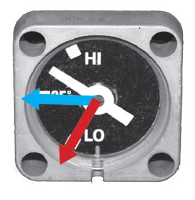
Figure 6
When considering liquid level, reading a level gauge is not quite as simple as seeing where the needle is pointing. It is necessary to include the relationship of the liquid level with respect to temperature. At 25°C, most level gauges have a horizontal pointer position. As the temperature rises, so will the “NORMAL” level position of the pointer. For instance, a transformer running at a 43°C top liquid temperature with a pointer position around the 25°C mark indicates a low liquid level and should be corrected as soon as possible.
When considering liquid level, reading a level gauge is not quite as simple as seeing where the needle is pointing. It is necessary to include the relationship of the liquid level with respect to temperature.
Independent of temperature, a liquid gauge with the needle resting on the bottom peg (red arrow) is either very low or the float on the lever has somehow failed. It is important to verify the level in this case. One method is using a long piece of clear tubing on the bottom valve with a vented tank. Raising it to the top of the transformer will show the exact liquid level.
Leaks are common in many older transformers as gaskets age and become brittle. If a leak develops on a radiator flange, repairing just that one radiator is not usually wise—especially on larger units and those subject to vacuum filling where the other gaskets may be well on their way to leaking as well. Scheduling an outage to bring in a field service provider is costly, so replacing all the gaskets in one trip is more economical.
Thermal Imaging Inspection
It was mentioned that another energized inspection is the infrared scan. This inspection is also reasonably inexpensive and has great harmony with liquid testing and visual inspections. A bushing or internal connection issue can show up on an IR scan. This can also be accompanied by an Ultrasound scan that can detect defects, including those caused by partial discharge.
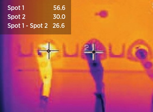
Figure 7
Inspection Findings
It is quite helpful to understand how the different diagnostics and inspections correlate. Let’s look at the low-level example and see how things tie together.
-
The level indicator, when considering the top liquid temperature, is normal to slightly low. If the level gauge were reading 25°C with the 60°C top liquid temperature, this would be a low level.
-
As shown below, the infrared scan shows a hotter-than-normal sidewall and a much lower-than-normal top radiator temperature. The top of the radiator and the sidewall at that height should have a similar temperature when proper cooling is present.
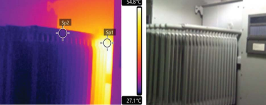
Figure 8
-
In time, overheating will show up in the combustible gas profile. Low-heating gases such as methane are expected.

Figure 9
-
Heat is also a part of the formula for oxidation. Acid and other oxidation byproducts are created over time with the presence of heat, oxygen, and moisture. The acids created in mineral oil are aggressive toward aging and decrease reliability in a transformer. Furans are indicators that the tensile strength of the paper insulation is under attack.
-
Additionally, the temperature of the liquid sample may be higher than the reading on the top liquid temperature gauge. This is due to the level having dropped below the gauge stem.
-
With many leaks, the pressure gauge may be at “0”. Depending upon where the leak is located, this may be a place for moisture ingress. Excessive moisture in a transformer lowers the dielectric properties of the transformer, aggravates aging, and should be addressed. Vacuum dehydration is not an IEEE-recommended solution unless it includes the vacuum dry out of the emptied tank. On-line dryers are effective in drying both vacuum and non-vacuum transformers.
-
Finally, platforms exist to bring all the data into presentations that show trends and give recommendations. NFPA 70B gives the minimum time-based guidance based on being Condition 1, 2, or 3. The frequency of testing varies based on the condition of the equipment.
Final Thoughts
Since the founding of SDMyers in 1965, we have found annual testing and visual inspections to be foundational aspects of stewarding transformer reliability for our customers. Visual inspections of transformer components are fundamental to any comprehensive maintenance strategy. Apart from meeting the basic requirements found in NFPA 70B, these activities help organizations increase the reliability and safety of their transformers—and, more importantly, the safety of workers who interact with them. Prioritizing visual inspections with technical excellence ensures transformers operate as intended for as long as possible and minimizes the risk of significant failures. In this way, organizations spend the least in the short term to get the maximum long-term value for their electrical power equipment.
Visual inspections of transformer components are fundamental to any comprehensive maintenance strategy.

Bob Rasor serves as Director of Transformer Services and has been with SDMyers since 1978, starting as a Product Design Engineer for oil processing equipment. Over decades he has held different leadership roles and reports to the President as the Technical Director for SDMyers. Bob is registered PE and serves on several IEEE Transformers Committee Working Groups, including the current chair for C57.106, the Insulating Fluids Guide.


